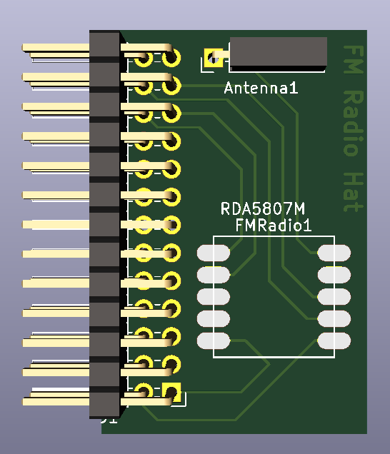
I had no idea how to design pcbs but it went extremely smooth with the free https://circuitmaker.com/
@spinal which software you ended using? I tried Eagle in Uni and it just frustrated me and I never tried again.
I think CircuitMaker is internally Altium, if I had a question I could follow Altium instructions. Generating the gerber has some quirks, I use https://oshpark.com/ to test the files (with their automated thing) first (and to order when I am in a hurry) but https://www.pcbway.com/ had been perfect for everything, specially for the price (5 USD, 10 PCS)
Here is the whole process: (circuit maker -> oshpark for checking (2d printed paper) -> pcbway)
Just a quick test with a multimeter, 0.38v. I’m reading with read_u16, then >>7 followed by a -7 to remove a small DC bias.
The only issues I’m having now is SD write speed for recording.
Which more or less confirms the 0.36V specification in the datasheet. That’s only a small fraction (about 1/9) of the ADC full scale reading capability, assuming it has a 3.3V reference. So, adding an op amp to boost the output voltage to swing something close the ADC’s full range may improve the quality of the sound that you capture.
It’s better to start with the best quality signal possible. A PWM output to the speaker circuit could resolve to 16 bits and you may wish to save 12 bit or 16 bit waveforms to SD.
Anyway, if you’ve got the real estate available on the PCB, it doesn’t cost anything to add footprints for an op amp circuit, even if you decide not to populate it.
If the reason you’re not using PEX pins I2C_SCL (P0_4) and I2C_SDA (P0_5) to control the radio is because you had trouble with conflicts with on board peripherals, it might be good to still allow using these pins by including jumpers for selecting them.
I would also connect the right output to another PEX analogue input pin. Although the Pokitto speaker/headphone output is only mono, you may wish to be able to record stereo. If you decide to amplify with an op amp you could use a dual package, such as the TLV2372.
If you decide to use an op amp on the output(s), you could put pads for both a SMD (SOIC or VSSOP) package and the DIP package, for flexibility.
Since the there’s only the RDA5807M IC, a crystal and a few passives on the radio module, you could put pads for these individual components within the pads for the module, wired in parallel. This way, either a module or (likely cheaper) individual parts could be used.
Have you written fully custom, optimised code driven by a timer hardware trigger and an ADC “acquisition complete” interrupt (as I’ve suggested numerous times), or are you still trying to use Pokitto library routines?
Well, that’s for continuous recordings. Someone may wish to buffer a portion to RAM and then write it to SD at their leisure. And, just because you’re having trouble today doesn’t mean someone won’t come up with a way to make it work.
There also may be other reasons to want to acquire stereo.
Anyway, it doesn’t affect your current capabilities if you add the ability to additionally capture the right channel output.
Oh, I get that people might want it as a possibility, I’ve added it to the diagram already. However, it seems a limitation of the system that recording more than a second or so of good quality audio seems impossible.
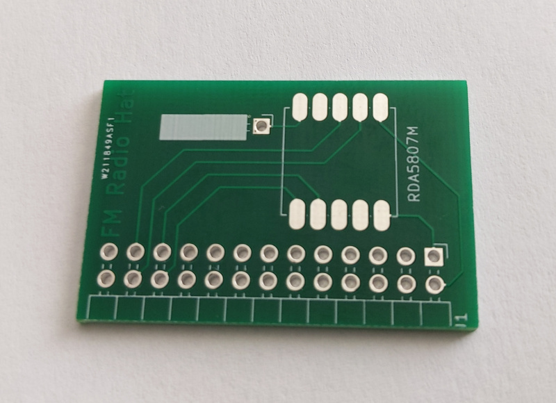
I’d put the antenna close to the module and keep the trace to it as short as possible. A long trace may affect reception.
Note that traces can come from the outside of pads or the sides of end pads. The 3.3V trace, at least, could benefit from this.
I’d also add a ground plane on both sides with flood fill. I’m not sure if you want it around or under the antenna, though. The information provided for the antenna may give some guidance about this.
I e ordered 5 from pcbway. Not expecting them to arrive any time soon, combination of health scare and cheapest shipping option will probably get here in time for the spare radio chips also from China in slow mail
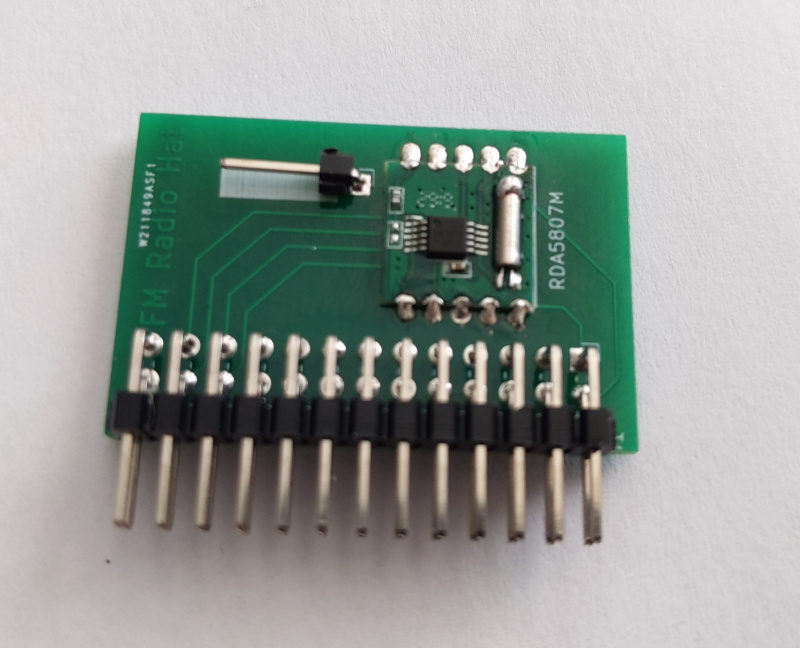
As it was my first PCBWay purchase, I got $5 off, the boards would have cost $5 + shipping, so they only cost the shipping, I chose the cheapest option , so $7 for the PCB’s. I already had a couple of the radio chips left, they’re usually around £2-£3 for 5 on ebay and the header connector I already had.
So for me the total cos was somewhere around £10 give or take. Although I now have 3 bare PCB’s waiting until my next 5 radio chips turn up some time in may (or longer).
I’m sure I’ve seen rumours that suggest that these sorts of PCB creation website can also assemble the boards, given that this radio hat has such a small part count, it would be ideal. But I can’t find any info on how to do that

 will probably get here in time for the spare radio chips also from China in slow mail