Does anyone have any suggestions for software to create PCB’s for those of us who want to make a more professional looking Pokitto Hat but have zero experience in the subject?
It probably goes without saying, but step one is to get it working on a breadboard with cables.
I know a guy on the Arduboy forums who’s been designing an ARM-based ‘homemade Arduboy’ who might have some insight into how to design and fabricate PCBs, I could ask him what his design and fabrication process is like if you want?
I think @uXe might also know a thing or two,
but I can’t remember whether he only uses FPGAs or whether he’s also done board fabrication.
Making a PCB is nowhere near as difficult as people think. I made first Pokitto myself on Diptrace with zero knowledge prior to starting.
Recommended tools, in no order of preference
Eagle PCB - “everybody” uses it, therefore lots of tutorials and ready examples how to export for PCB manufacturing, many times can be uploaded directly as eagle files
KiCAD - fast growing in popularity. Lots of users, better UI (in my opinion) than Eagle
DipTrace - used to be my choice but is losing to KiCAD
As for making a PCB, it is so cheap and so fast and easy that IMHO you can bypass the breadboard phase completely
I used PCBway, nothing but positive to say
Edit: in short, stop thinking, download one of the packages and just do it. You will be ordering a board in less than a week
This is probably one of the problems people have.
If you haven’t made a PCB before then you aren’t likely to know what software is available,
let alone how to use it.
And of course if you’re inexperienced you’re unlikely to know the potential pitfalls,
like how far apart to keep the ‘traces’. (I think that’s what they’re called? The conductive lines.)
All of the above packages will analyze such things for you. Furthermore, when you order PCB’s the PCB manufacturers will also analyze and report such issues.
Have you done any testing on the input voltage range that the ADC receives from the radio? You could do this by saving max and min values on each ADC reading. If you’re only getting a fraction of the ADC full scale value (4096 for 12 bits), then I’d add an op amp to the board to boost the radio output.
You’ve got lots of space, so it wouldn’t hurt to at least add the pads for an amp (plus the required support components). You could also include a solder jumper that shorts the input to the output in case you decide to not populate the amp.
I’d consider the TLV2371 for starters but there are plenty of other choices with the same pin out that would just drop in.
I had no idea how to design pcbs but it went extremely smooth with the free https://circuitmaker.com/
@spinal which software you ended using? I tried Eagle in Uni and it just frustrated me and I never tried again.
I think CircuitMaker is internally Altium, if I had a question I could follow Altium instructions. Generating the gerber has some quirks, I use https://oshpark.com/ to test the files (with their automated thing) first (and to order when I am in a hurry) but https://www.pcbway.com/ had been perfect for everything, specially for the price (5 USD, 10 PCS)
Here is the whole process: (circuit maker -> oshpark for checking (2d printed paper) -> pcbway)
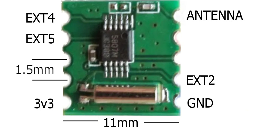
Just a quick test with a multimeter, 0.38v. I’m reading with read_u16, then >>7 followed by a -7 to remove a small DC bias.
The only issues I’m having now is SD write speed for recording.
Which more or less confirms the 0.36V specification in the datasheet. That’s only a small fraction (about 1/9) of the ADC full scale reading capability, assuming it has a 3.3V reference. So, adding an op amp to boost the output voltage to swing something close the ADC’s full range may improve the quality of the sound that you capture.
It’s better to start with the best quality signal possible. A PWM output to the speaker circuit could resolve to 16 bits and you may wish to save 12 bit or 16 bit waveforms to SD.
Anyway, if you’ve got the real estate available on the PCB, it doesn’t cost anything to add footprints for an op amp circuit, even if you decide not to populate it.