Introduction:
When learning programming it is customary to write a ‘hello world’ program - a simple demonstration of how to output text.
For electronics I think it is appropriate to use a similar approach of doing something with a simple output, hence this tutorial will show you something very simple: how to turn on a light.
Components:
For this project you will need…
- 1 Pokitto
- 1 Breadboard
- 1 LED (Light Emitting Diode, can be any colour, must the 2-legged variety)
- 1 220 Ohm Resistor (Colour coded: Red Red Brown)
- 2 Long jumper cables (preferably different colours)
You will also need a flat work surface, something to keep your parts in (a small box or bag), and a way to program your Pokitto.
(I will be writing my code in EmBitz, but you are free to use an alternative, the result should be the same.)
Diagrams
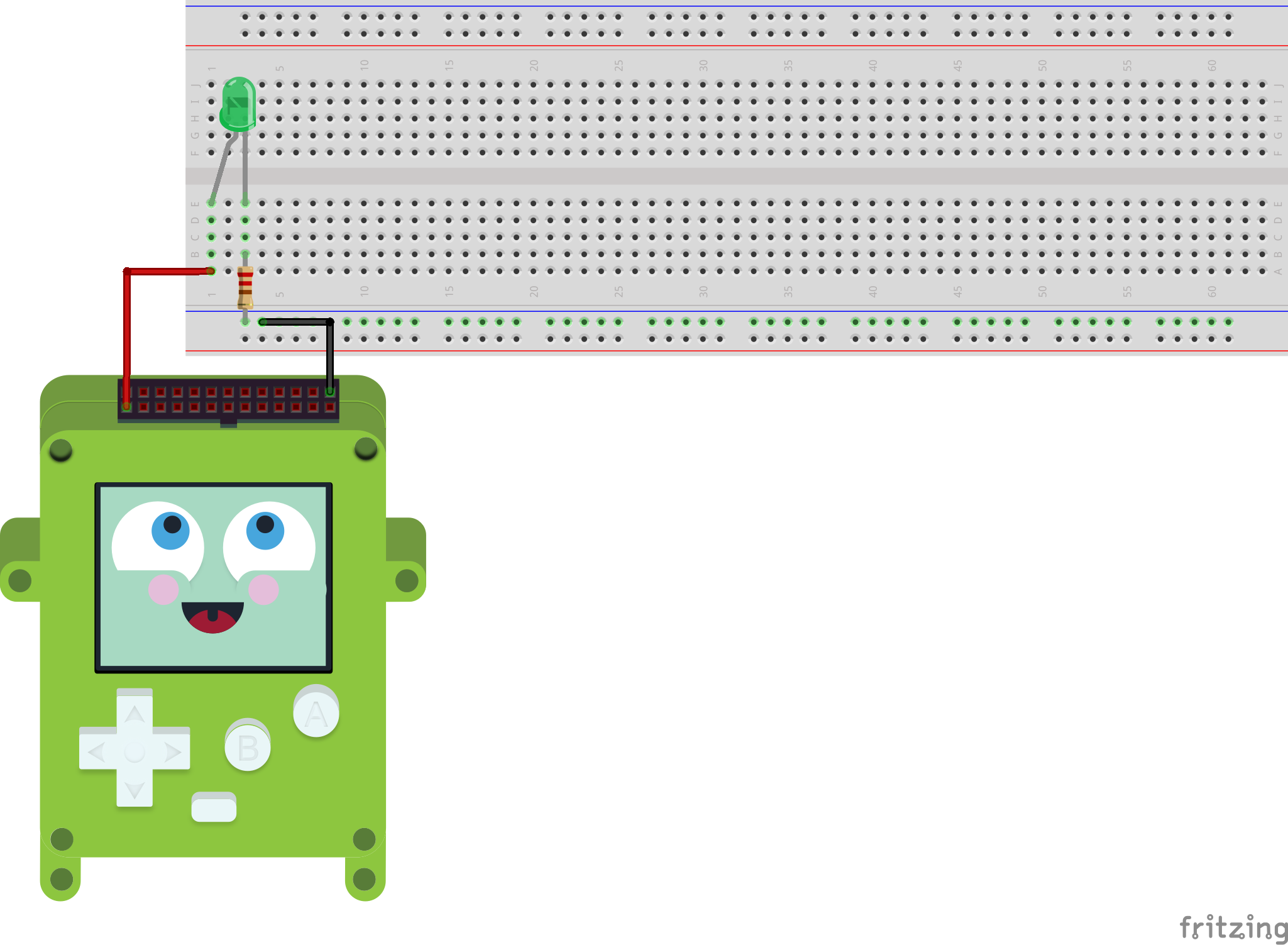
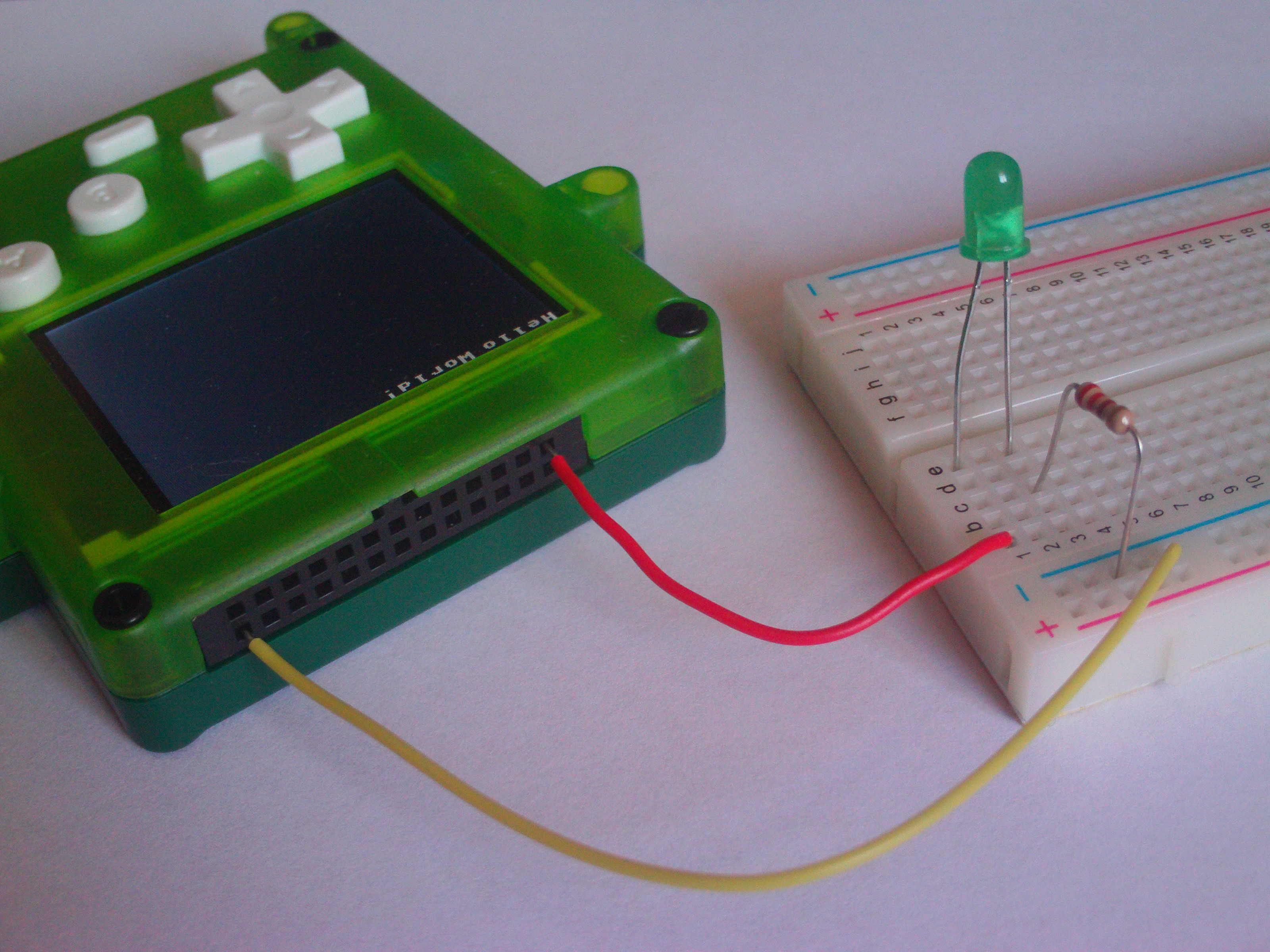
Here’s a preview of what the final circuit should look like:
About The Components:
What Is A Breadboard?
A breadboard is a simple tool used for prototyping circuits by plugging wires and components into the board to create a circuit. Breadboards are popular for prototyping because they’re very easy to use, electronic components can be easily inserted and removed with very little risk.
Essentially breadboards are little bricks of plastic covered in holes. Beneath the holes there are lines of conductive material that connect certain holes together in a pattern. These lines allow electricity to flow and thus components plugged into the board to connect to each other. It’s important to remember the pattern for your breadboard because you need to make sure you know which components are connected to each other.
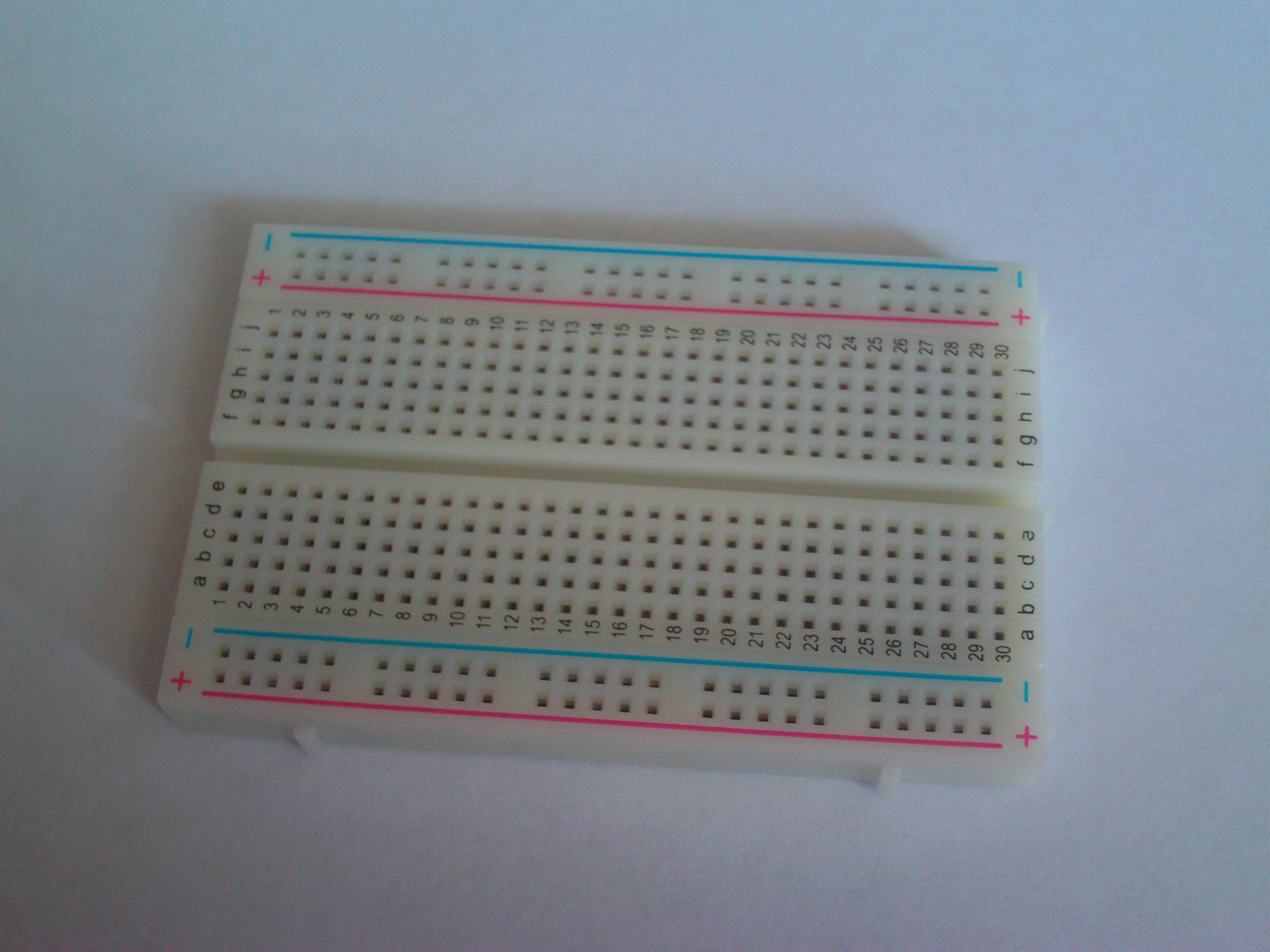
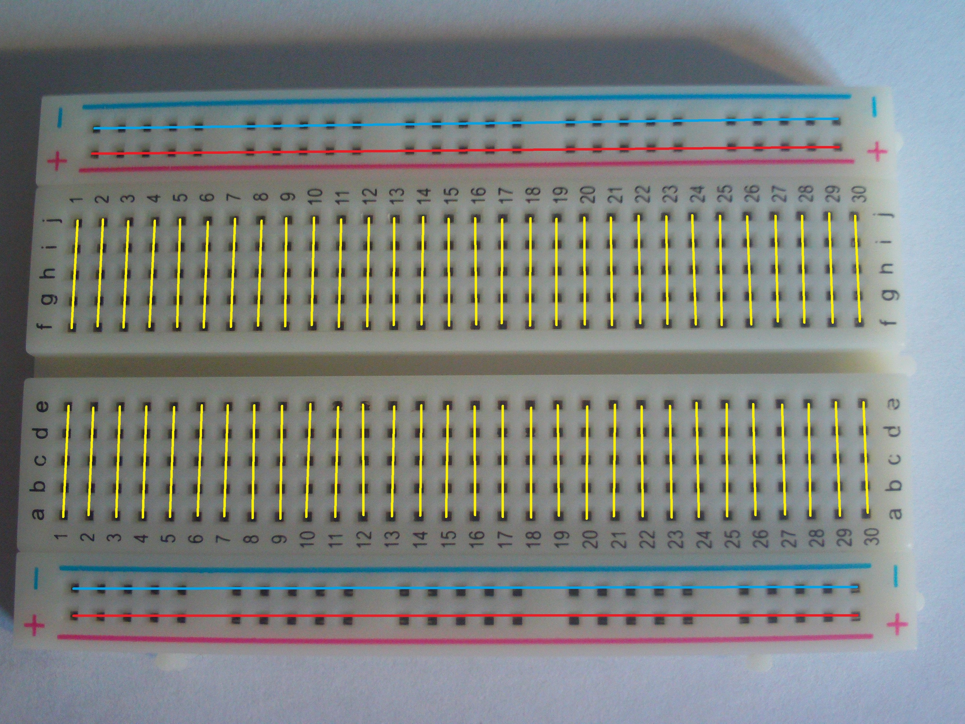
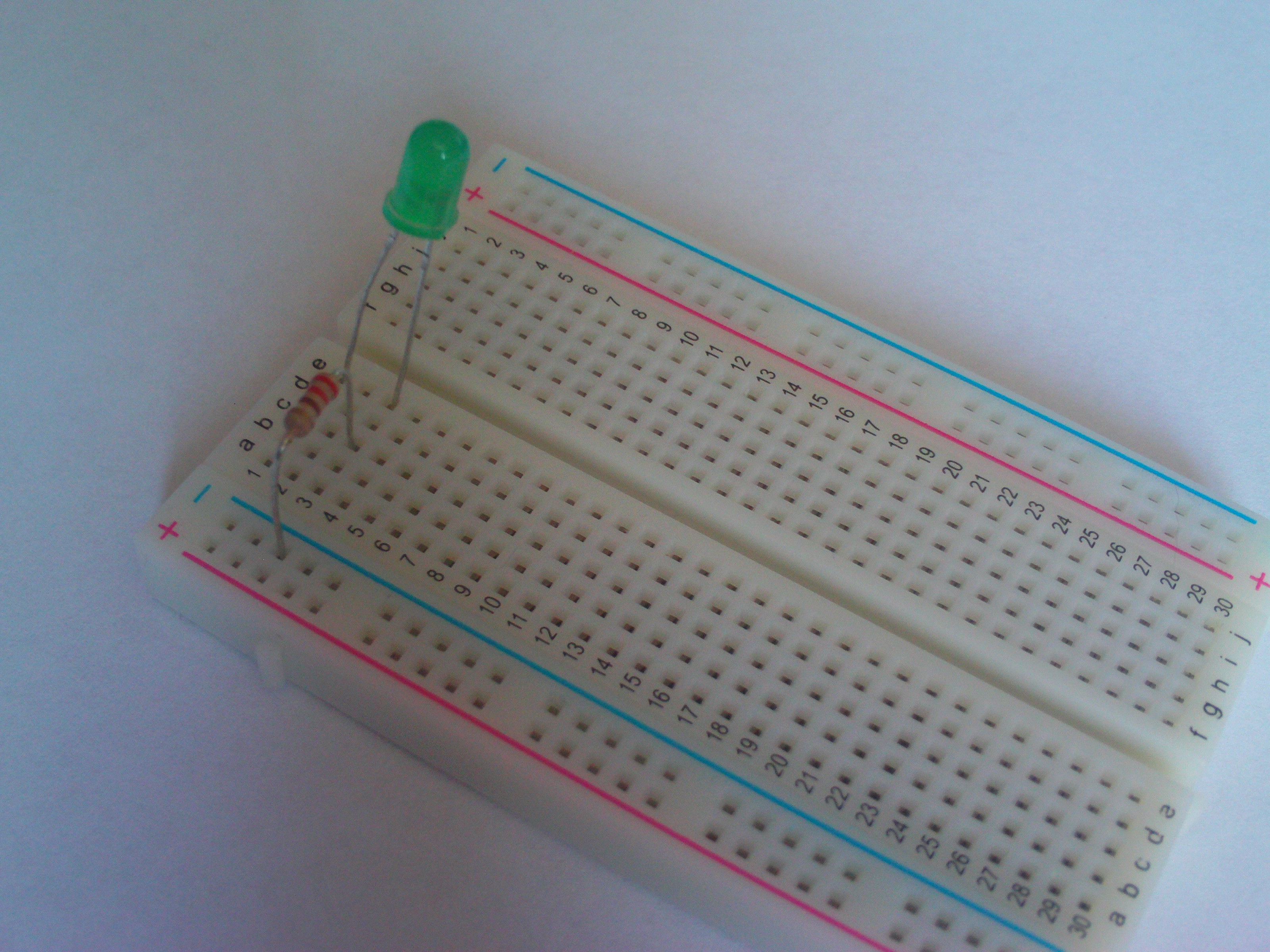
This is the line layout of the board I will be using in this tutorial.
Look back at this image if you find yourself struggling to understand how the components.
What Is An LED?
Modern circuits, especially small circuits, tend to use a thing called a light emitting diode (LED) to produce light. Essentially an LED is just another kind of light-emitting device, much like a regular household lightbulb.
LED vs ‘Normal’ Lightbulb
The kind of lightbulb you’ll find being used in the lights in your house is probably either a halogen or an incandescent bulb, both of which produce light by heating a metal filament which in turn heats gas stored inside a transparent shell.
LEDs work differently, they use electricity to cause a reaction that releases photons (particles of light) at the atomic level, and thus don’t produce as much heat or require as much energy so they’re safer to work with and better for use with low energy circuits and technology.
What Is A Resistor?
A resistor is a component that is used to resist the flow of electricity. They have many different uses, usually they are used for protecting components from damage, but special-purpose resistors can do things like detect light levels or temperature.
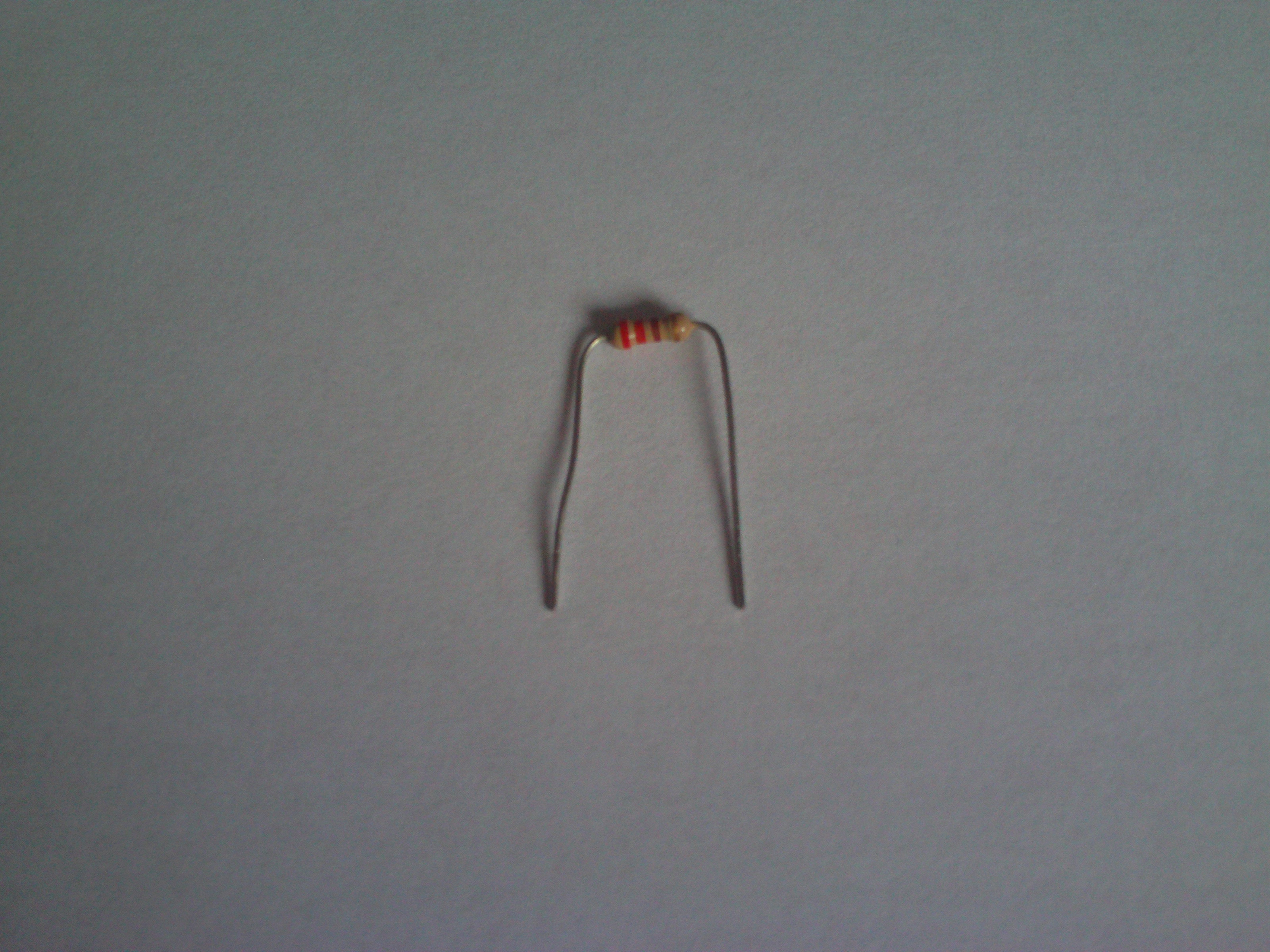
For this tutorial you will only need a normal resistor, the kind that looks like a little beige cotton spool.
This kind of resistor is colour coded to show precisely how much it resists electrical flow. Resistance is measured in ohms and for this tutorial you will need a 220 Ohm resistor, which is typically colour coded as red, red, brown, gold (though other combinations are possible).
Reistors can be hard to understand if you don’t know the details of how electricity works, but that’s another problem for another time.
Instructions - The Circuit:
Before you start make sure you have your flat work surface ready and that all your parts are present and correct and inside your chosen container.
Step 1 - The Breadboard
Firstly, place your breadboard on your flat surface.
Step 2 - The LED
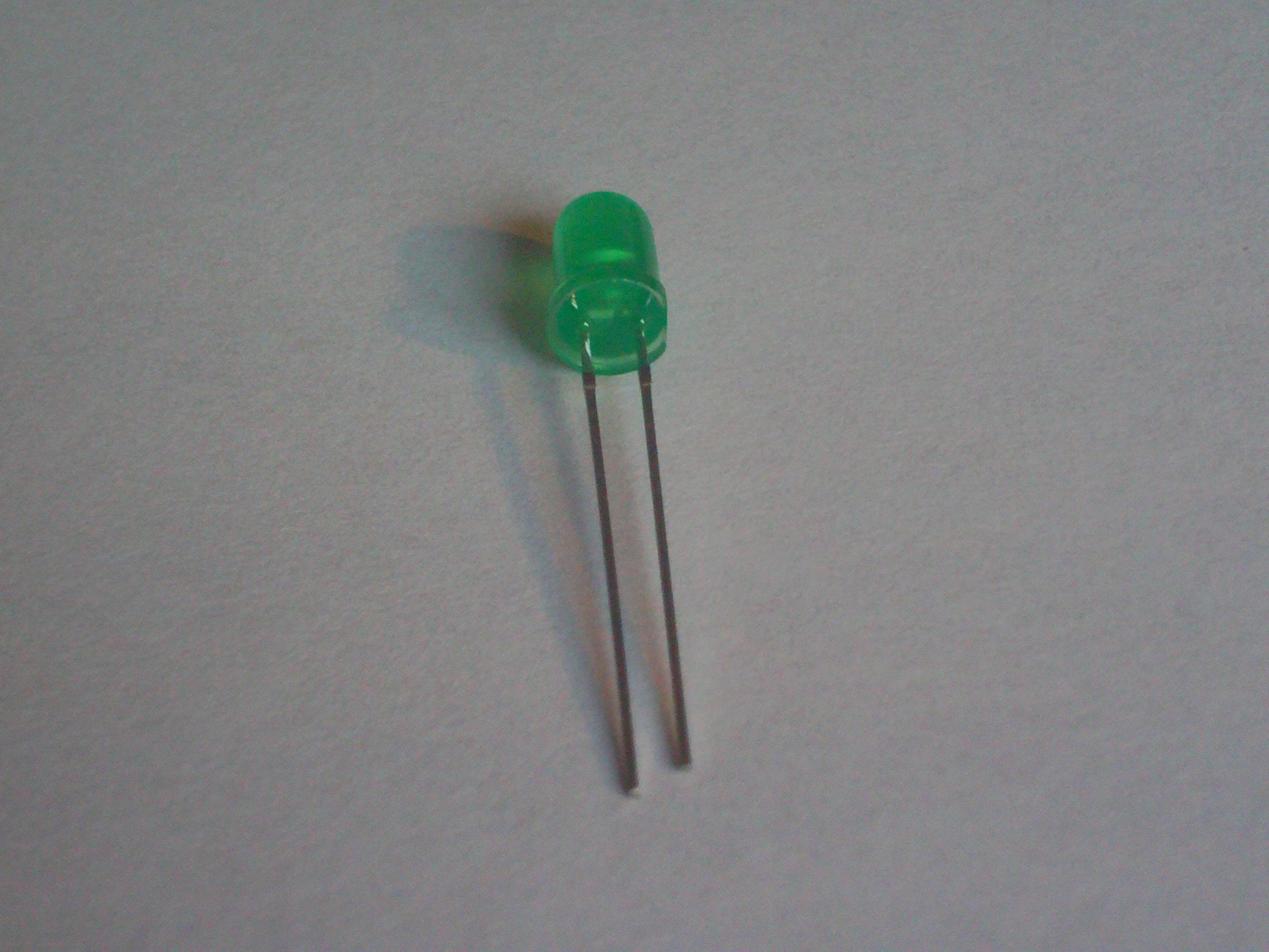
Next, locate your LED and look at the legs. You will probably notice that one is longer than the other.
The longer leg is called the ‘anode’ and the shorter leg is called the ‘cathode’.
When the circuit is connected up, the ‘anode’ is the part that will be connected to ‘power’ (in this case one of the Pokitto’s extension slots, EXT 0) and the ‘cathode’ is the part that will be connected to ‘ground’.
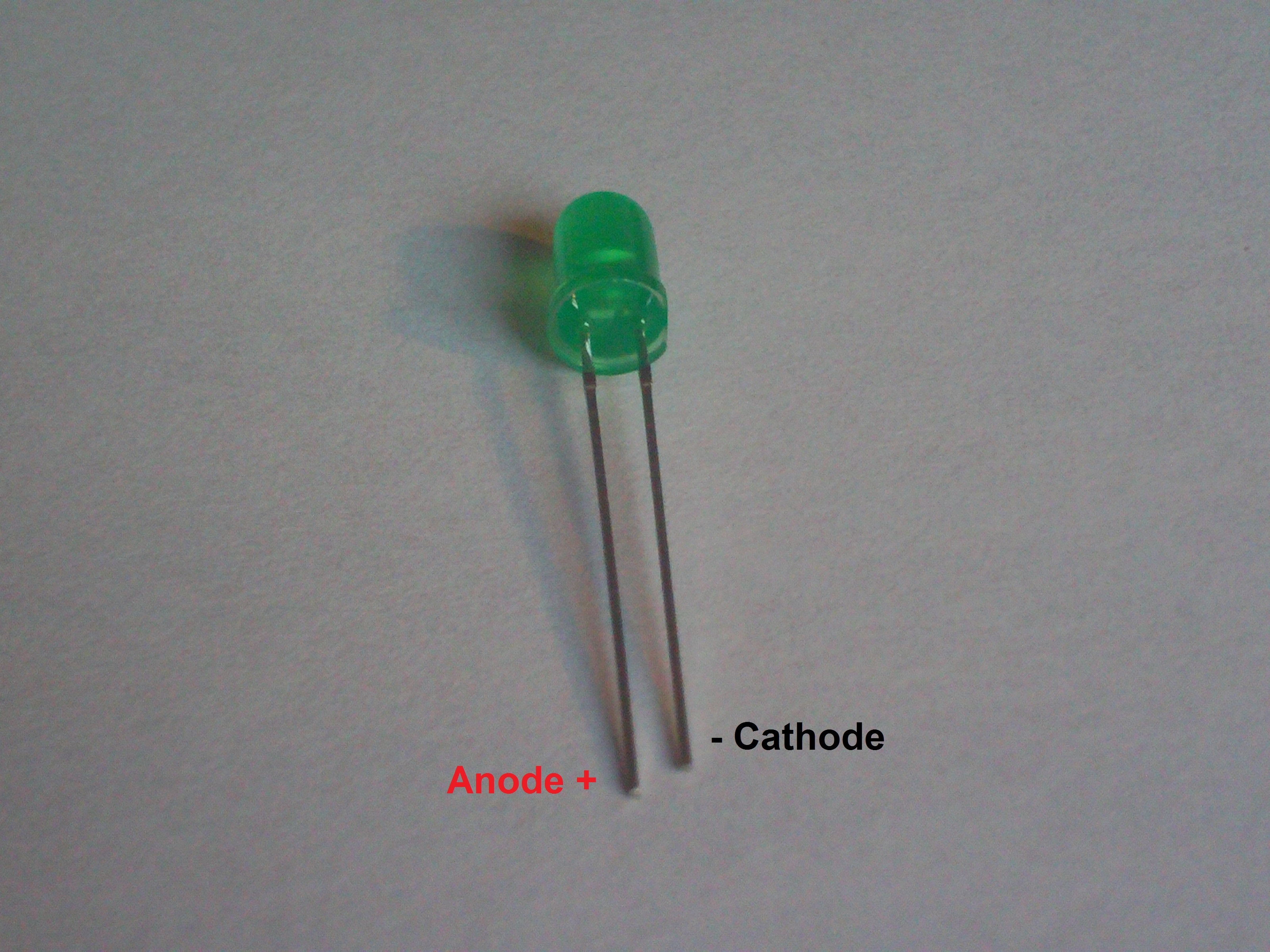
It is important to get them the right way round or the LED won’t light up.
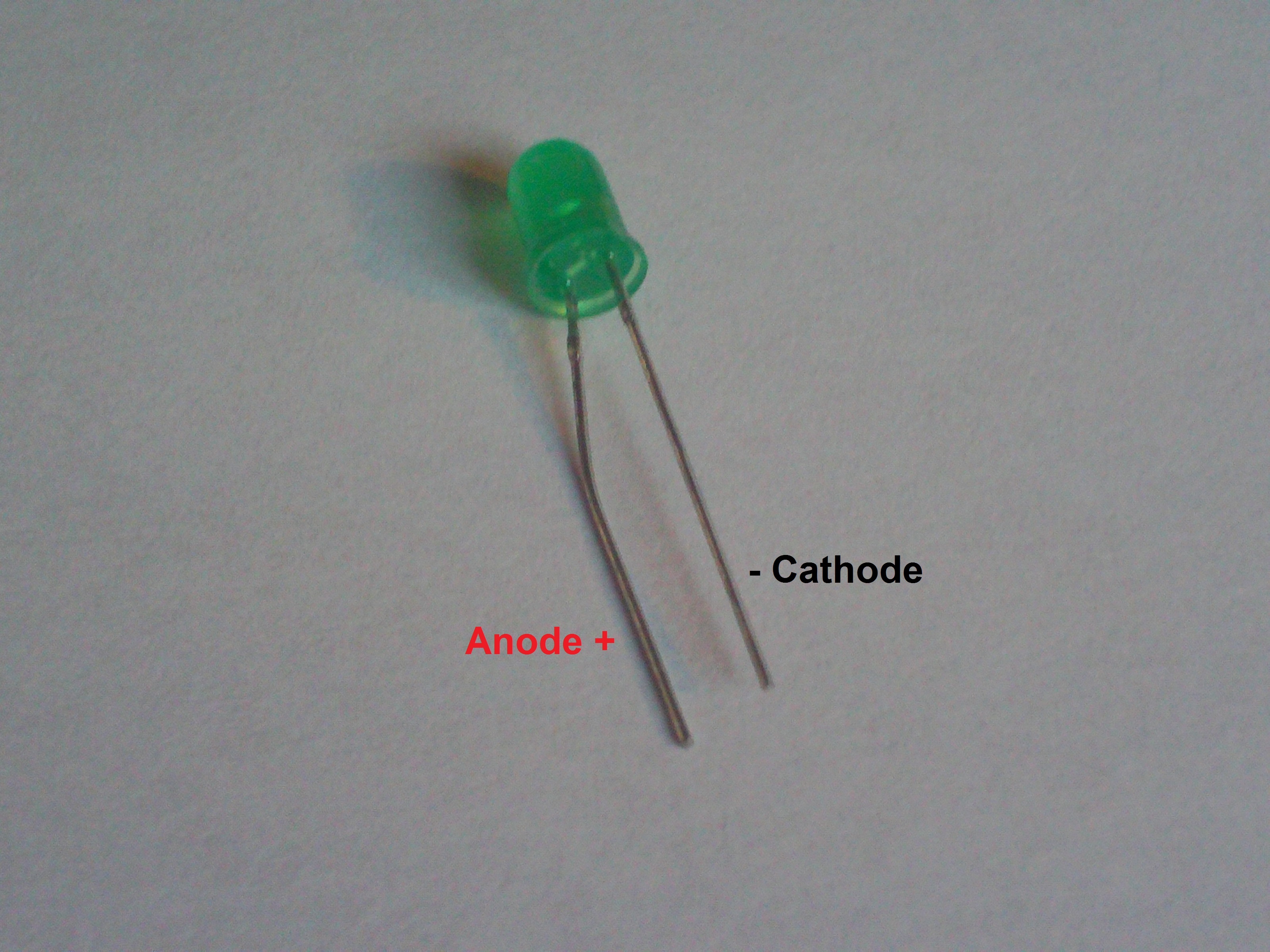
When putting your LED into the circuit, you’ll probably have to bend the legs slightly.
Don’t worry if you do, they are designed to be flexible.
Try not to bend them too much though - you need to be able to tell the legs apart.
I find the best approach is to only bend the anode (the long leg) if possible, which tends to leave you with a shape like this:
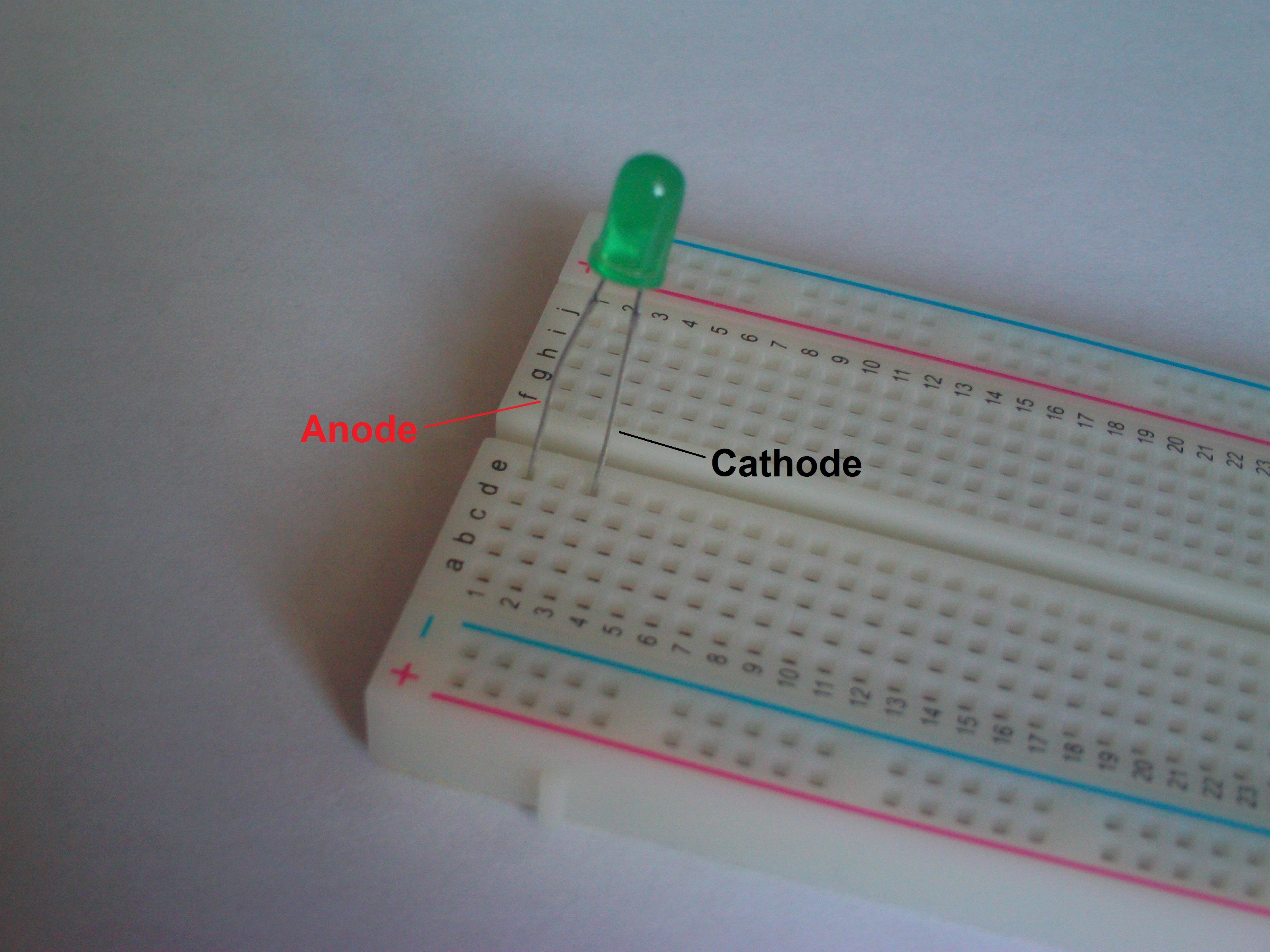
And now simply insert your LED into your breadboard like so:
Step 3 - The 220 ohm Resistor
Next you will need to take your 220 ohm resistor and connect it between the neutral line of the breadboard and the line that the LED’s cathode (the short leg) is connected to.
The reason for doing this is to protect the components in the circuit from damage that would occur if the flow of electricity wasn’t being resisted somehow. In this case, if the wrong resistor was used or there was no resistor at all, the LED could burn out and become unusable.
Step 4 - The Pokitto
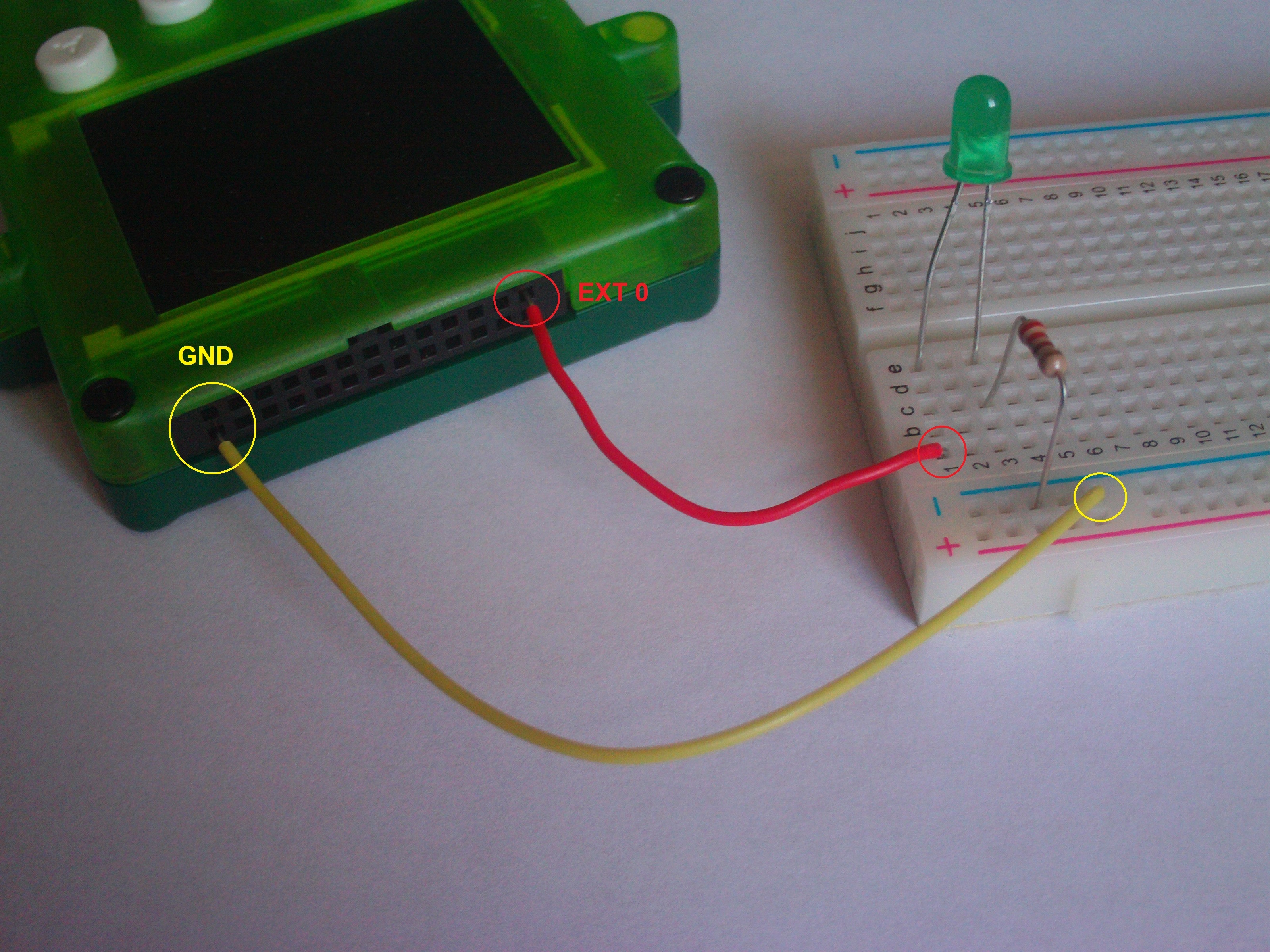
Next you take one of your jumper wires, connect one end to the negative/ground line on the breadboard and connect the other end to the ground pin in the Pokitto.
Then you take the other jumper wire, connect one end to the same line as the LED’s anode (the long leg) and connect the other end to the Pokitto’s EXT 0 pin.
Which should look something like this:
Congratulations, your circuit is now complete!
However, the Pokitto still needs to be programmed to interact with your circuit.
Instructions - The Code
Normally in a programming tutorial I’d step you through the creation of the code to explain what it all does, but I’m going to break the rules here and start by just giving you the code since you should already have an idea of how to do some basic programming before starting this tutorial.
// The Pokitto library
#include "Pokitto.h"

// The Pokitto Core library object
Pokitto::Core pokitto;

// Create a 'DigitalOut' object to represent the
// digital output pin used to communicate with the LED
// The object is set to use the EXT0 pin for output
DigitalOut led0 = DigitalOut(EXT0);

// The main function
int main ()
{
	// Initialise the Pokitto
	pokitto.begin();

	// The main loop
	while (pokitto.isRunning())
	{
		// update the Pokitto's state
		if (pokitto.update())
		{
			// write 'Hello World!' to the screen
			// this is so you can tell the Pokitto is running
			pokitto.display.print("Hello World!");

			// If the A button is pressed
			if(pokitto.buttons.aBtn())
			{
				// Send a high signal to turn the LED on
				led0.write(1);
			}

			// If the B button is pressed
			if(pokitto.buttons.bBtn())
			{
				// Send a low signal to turn the LED off
				led0.write(0);
			}
		}
	}

	return 0;
}
Explaining The Code:
Here the code is using the DigitalOut class, which is a class provided to all mbed-compatible boards.
It represents a digital output connection.
To initialise it you simply tell it which pin you want to use, which can be any of the Pokitto’s EXT pins (all 18 of which, EXT0 through to EXT17 are pre-defined in the Pokitto.h header).
For this tutorial though it must be EXT0 because that’s the slot you’ve wired up.
DigitalOut led0 = DigitalOut(EXT0);
To control the output pin’s output the write function is used on the pin.
Writing a 1 raises the power on the pin which then turns the light on (this is also known as a ‘high’ signal).
Writing a 0 lowers the power on the pin which then turns the light off (this is also known as a ‘low’ signal).
// If the A button is pressed
if(pokitto.buttons.aBtn())
{
	// Send a high signal to turn the LED on
	led0.write(1);
}

// If the B button is pressed
if(pokitto.buttons.bBtn())
{
	// Send a low signal to turn the LED off
	led0.write(0);
}
Information about the other functions and code constructs used here can be found in another tutorial.
The Result:
Once the code has compiled correctly and you have it loaded on to your Pokitto you can wire the Pokitto back up and begin testing the code.
If you have wired everything up correctly and the code compiled properly then the LED should turn on when you press the A button and turn off when you press the B button.
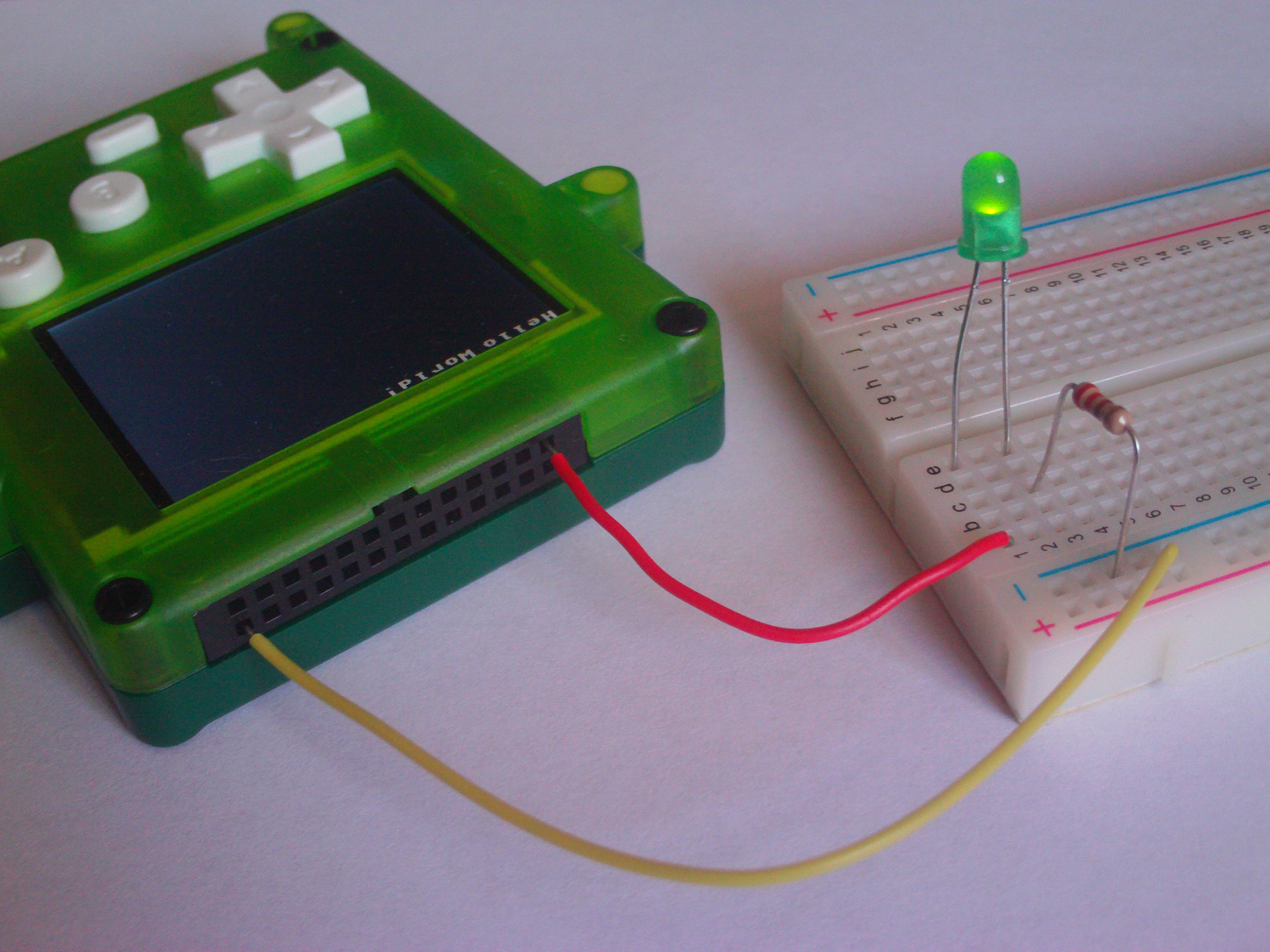
Congratulations, you have successfully used the PEX!
To make sure you know how the electricity is flowing, here’s a picture demonstrating the flow of electricity with arrows:
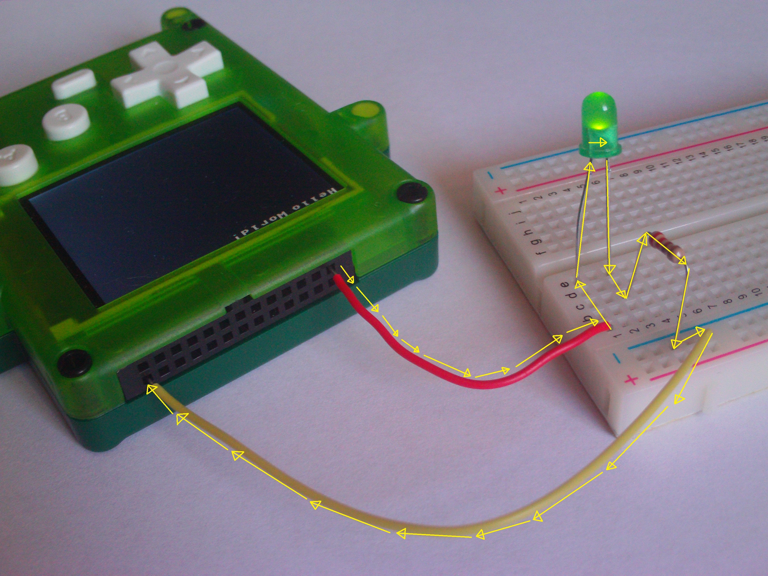
The Pokitto (like most computers and computer-like devices) uses something called ‘direct current’ which means the electricity flows in only one direction.
It is possible for electricity to flow in both directions (which is called ‘alternating current’) but that’s not very useful for most computers so that’s an issue for another day.
Do It Yourself Challenges:
Now that you’ve got a working circuit, why stop there?
Why not test how much you understood by having a go at these challenges?
(Note that not all of the information to complete these challenges can be found in this tutorial, you might have to read some others first and come back to the challenges.)
Code challenges:
- Wire the LED up to a different Pokitto pin
- Change the buttons used to turn the LED on and off
- Set a single button to ‘toggle’ the light on and off
Code + Circuit challenges:
- Add a second LED connected to a different Pokitto pin