Introduction to PEX - the Pokitto EXtension header
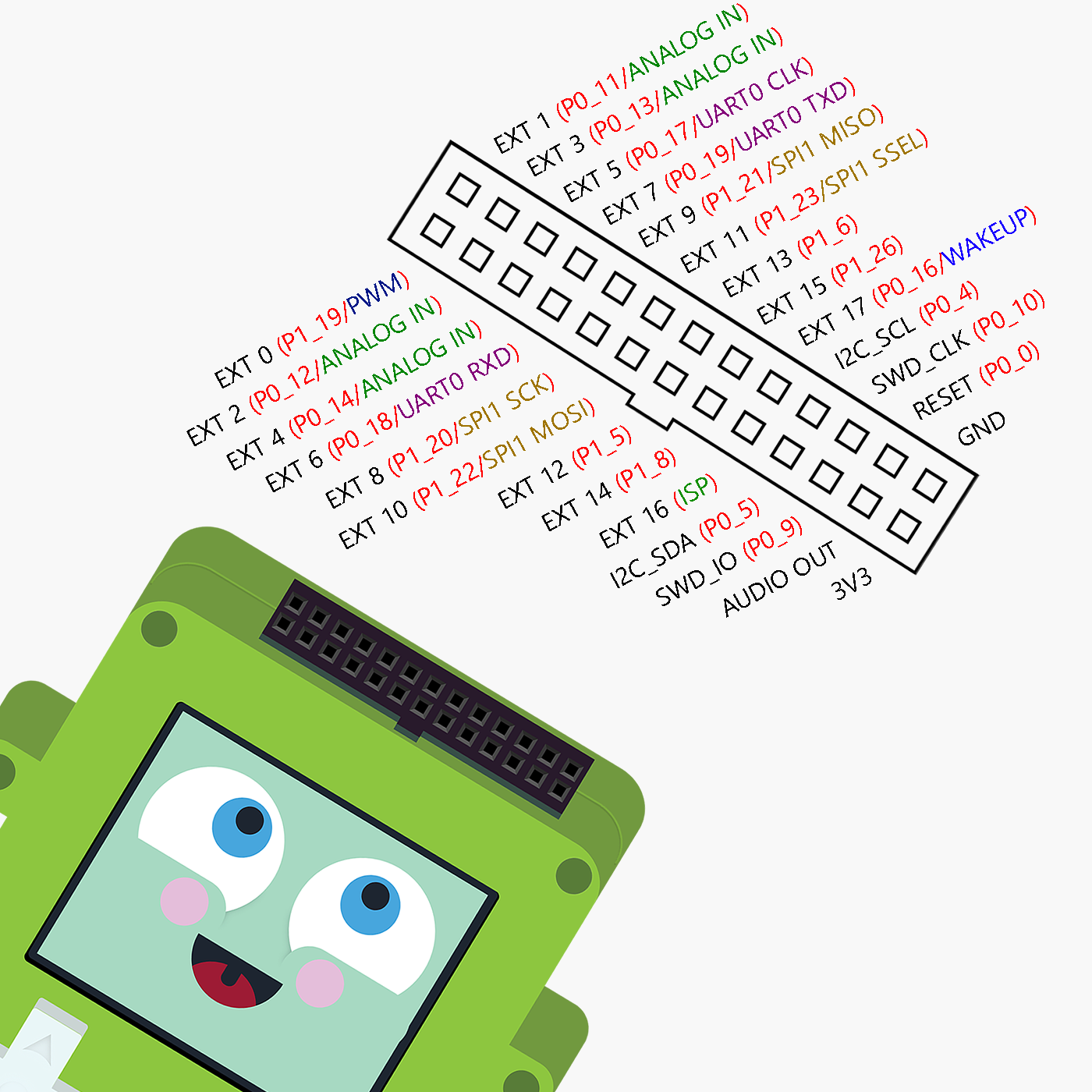
Pokitto EXtension header (PEX) provides a way to extend the functionality of Pokitto. The header uses a common 0.1 inch pitch - you can connect many electronic components to Pokitto simply by wiring them directly to the PEX. For example, you could add ten buttons to create a multiplayer Snake game:

PEX extension header - what are “pins”?
The holes in the PEX header are called “I/O pins”. Each “pin” is somehow connected to the main Pokitto processor, called a ARM Cortex microcontroller. You can talk to the processor, give it inputs and read output from the processor. This means you can use Pokitto to directly read temperature sensors, GPS sensors, accelerometers, control servos and motors etc. “I/O pins”, or sometimes called IO pins or GPIO pins, therefore simply stand for “Input and Output pins”
The ability to connect directly to the “nervous system” of the processor is a special feature of the microcontroller. If you take a processor from a phone or a tablet, they are much more powerful but also much much more fragile and complicated. To connect electronics to them is complicated and you can easily kill the chip with just static electricity. Microcontrollers on the other hand were designed exactly for this reason - to provide an easy and more robust way to control physical gadgets.
Meaning of the P0_11 etc. names
You may be wondering what does an abbreviation like P0_11 mean. It is actually very simple. The I/O pins of the ARM Cortex are divided into groups called ports. So P0_11 means “pin 11 of port number 0”. And P1_23 similarily would mean “pin 23 of port number 1”.
Why do we need ports and pins? Why can’t we just name pins with simple names like Pin 0 to Pin 100? The reason for this is in the internal structure of the ports. If I want to make a number of pins do an operation really fast I can give a value to the port and change many pins at once. For example, if I send a value 15 to port number 0, that value is 1111 in binary. That value will set pins 0, 1, 2, and 3 of port 0 at the same time, with one call! That is why we have the pins grouped as ports. Its to make things faster and allow us to change many pins at the same time. This is how the LCD of the Pokitto operates.
Meaning of EXT0 … EXT17
If you read the previous paragraph, you now know that pins are named like this: Px_y, where the y is the pin number and x is the port number.
This can sometimes get a bit tiresome, because you really do not need to know each and every pin port number to be able to use the GPIO pins. That is why short names EXT0 to EXT17 are provided.
Let’s say you want to control a LED light, and you want to use the first pin in the Pokitto PEX header to turn the light on and off. You could declare this control pin like so in your program:
DigitalOut myled(P1_19);
but that’s kind of silly, having to remember the first pin is P1_19.
Instead, with the EXT naming system, you can simply do:
DigitalOut myled(EXT0);
…and it does exactly the same thing!
Meaning of PWM (EXT0 pin special function)
PWM stands for Pulse Width Modulation. This topic is too complicated to explain here in detail, but the idea is this: microcontrollers do not output analog signals (meaning a continuous voltage from 0 to 3.3V, say for example 1.65V). What they out put is logical 1 (3.3V) or logical 0 (0V). Microcontrollers output a digital signal meaning its just ones and zeroes!
But what if you are making, for example a LED light dimmer control, and you need 1.65V to make the light 50% dimmer than at full power (3.3V)? This is where PWM comes in.
Imagine you switched on the light for one second, then turned it off for one second. Your room would get only 50% of the light, correct? But it would be kind of annoying, because of the blinking. But what if you did it really fast - so fast that your eyes can’t see when the light is on or off - for example, turned the light on and off 1000 times per second? The result would be that the light would appear to be only half as bright - and this how PWM works.
Meaning of ANALOG IN (EXT1…EXT4 special functions)
Analog in pins can be configured as analog signal inputs like so:
AnalogIn ain(EXT1);
Microcontrollers were originally invented to read digital signals, but soon also included an Analog-to-Digital A/D converter to read analog inputs, such as data from temperature sensors, light brightness sensors, motor current resistance etc. Reading analog signals was, and continues to be, one of the the main jobs of microcontrollers. This is why also Pokitto has several ADC converters built inside of it. ADC stands for Analog to Digital converter.
It is important to understand that ADC (analog to digital) is a standard feature of all microcontrollers, but the reverse DAC (digital to analog) is not the same thing! Pokitto has a DAC that can be used (it is the audio signal) and PWM on EXT0 so that you can output an analog signal if you need it!
Meaning of UART (EXT5…EXT7 special functions)
UART stands for “Universal Asynchronous Receiver-Transmitter” protocol. UART protocol is an old “language” that was invented to allow computers to talk to each other. Pokitto can also talk UART. With UART, you can use a computer terminal program to talk to Pokitto through the UART pins or use Pokitto to control other devices that understand UART.
UART pins are:
- CLK - the clock signal, used to synchronize the two devices talking with each other
- RXD - received signal (incoming)
- TXD - transmitted signal (outgoing)
Meaning of SPI (EXT8…EXT11 special functions)
SPI stands for “Serial Peripheral Interface”. It is a protocol like the UART, and you can read more about it here.
The SPI is a different kind of protocol than the UART. The UART is a complicated and polite protocol, that works like this:
“Hello Sir?”
“Yes Watkins, what is it?”
“Are you ready to receive a message?”
“Certainly my good man!”.
The SPI is not like that at all. It is a single pipe of data from Master to Slave (MOSI) and optionally another pipe from Slave to Master (MISO) and as long as the clock signal (SCK) is ticking each pipe is pumping data from one to another! In addition, there is one more wire, called “Slave select”. Each slave (and there can be several), has its own select line. When the select line of the slave is low (0V) it means that slave is listening to the instructions from the master.
SPI pins are:
- SPI SCK - SPI clock signal, that “pumps” the data at intervals
- SPI MISO - SPI Master In, Slave Out. Message pipe from slave to master
- SPI MOSI - SPI Master Out, Slave In. Message pipe from master to slave
- SPI SSEL - SPI Slave Select. When this line is low, slave must listen to instructions from master
Before you go: be aware of difference between 3.3V and 5V voltages in electronics
Electronics work by sending and listening to streams of digital data as ones (1) and zeros (0).
Zero is also often called “low”. A low signal means that the pin or wire carrying it has 0 volts at that time. “High” on the other hand represents one. When a signal is “high” it means that the wire or pin carrying it at that time is at the operating voltage of the system. Pokitto is a modern ARM Cortex-M0+ chip: for Pokitto “high” means 3.3V.
Many Arduino projects use 5 Volt components, because the chip used in Arduino Uno are old 8-bit technology (more modern Arduino boards, such as Arduino Zero, are also using 3.3V, just like Pokitto) The change from 5V to 3.3V was done to save energy and make modern electronics run longer from battery power.
A 5V signal carries much more energy than a 3.3V signal. If you connect a 5V signal to a chip that is meant to run at 3.3V, the resulting heat can damage the silicon chips. Therefore, be warned that connecting 5V signal to Pokitto PEX pins can immediately damage your Pokitto.
Always Check the components that you are connecting to the Pokitto are using 3.3V