Introduction:
Now that you’ve got your head around digital signals, it’s time to move on to analogue signals.
Whereas digital signals represent the values of 1 and 0 using high and low input voltages,
analogue signals represent a continuous range of values by varying the input voltage.
In other words, reading an analogue input value will give you a range of numbers rather than just a 1 or 0.
In this tutorial I will be showing you how to make a potentiometer-driven dial display.
Components:
For this project you will need…
- 1 Pokitto
- 1 Breadboard
- 1 Potentiometer (preferably a ‘thumwheel pot’/‘thumb pot’ type)
- 2 Short jumper cables
- 3 Long jumper cables (preferably different colours)
You will also need a flat work surface, something to keep your parts in (a small box or bag), and a way to program your Pokitto.
(I will be writing my code in EmBitz, but you are free to use an alternative, the result should be the same.)
Diagrams
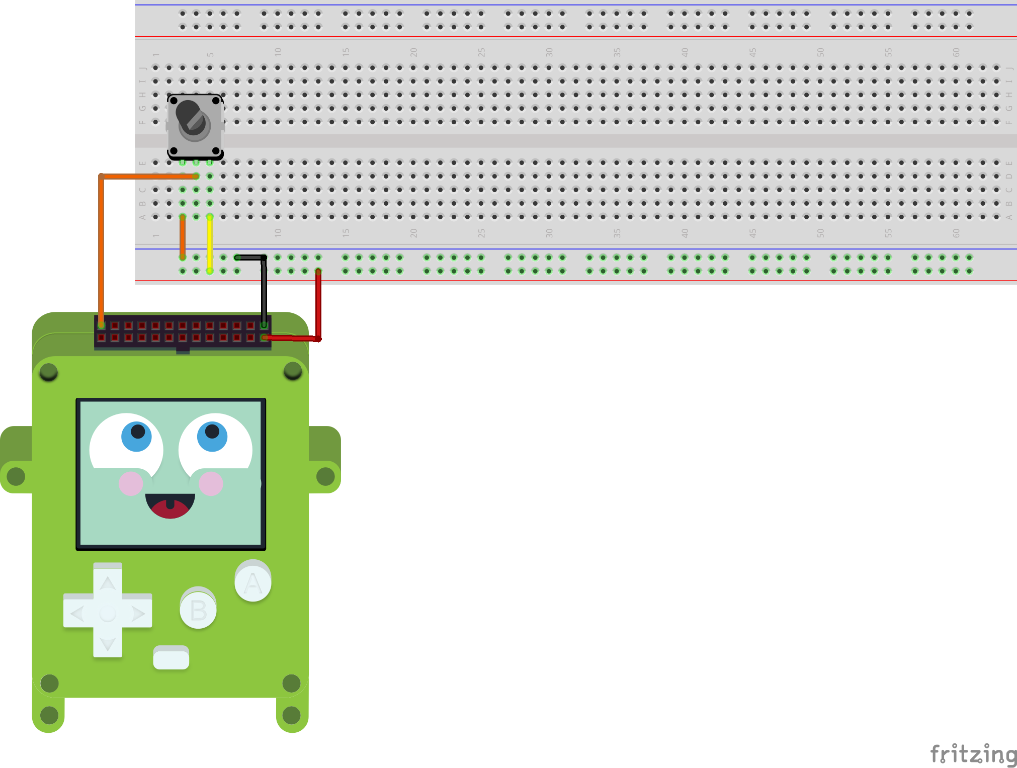
Here’s a preview of what the final circuit should look like:
About The Components:
What Is A Potentiometer?
A potentiometer is the analogue equivalent of a button.
With digital electronics a button provides the full range of digital values (1 and 0) via a simple input mechanism.
In analogue electronics the potentiometer does the equivalent - providing the full range of analogue values via a simple input mechanism.
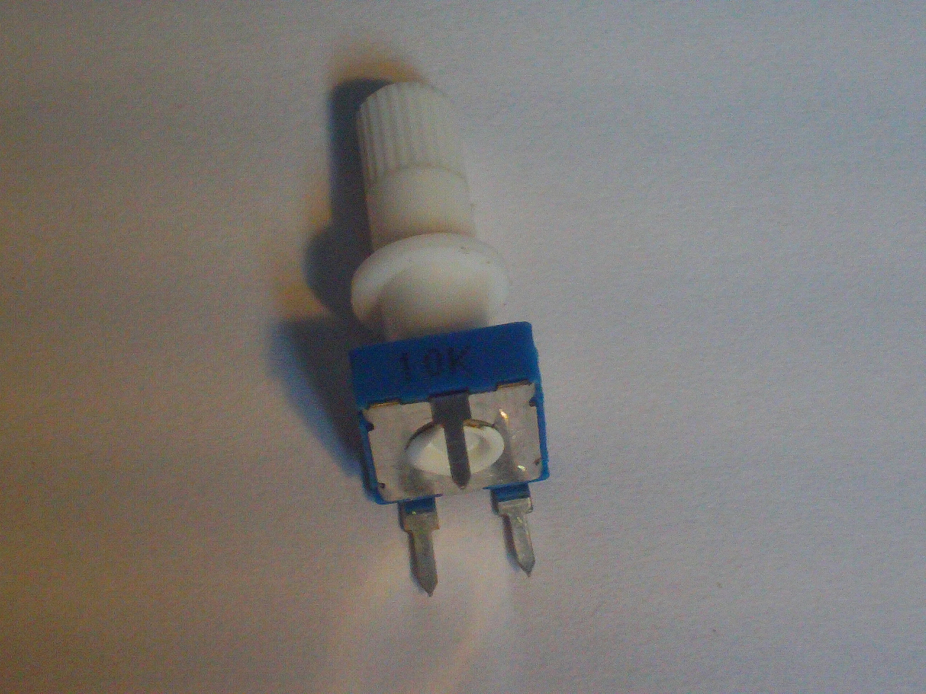
Technically speaking a potentiometer is actually a special kind of adjustable variable resistor, hence they often have their resitance value (in Ohms) stamped on the side.
Generally potentiometers can be classified into two varieties: slidable and rotary.
Slidable potentiometers function by sliding a grippable part along a constrained axis.
Rotary potentiometers function by rotating or turning a grippable part in a clockwise or anticlockwise direction.
Although there are two main varieties, there are also many different specific types of potentiometer:
- A trim pot (or trimmer pot) is a potentiometer that has a screw head so it can be adjusted with a screwdriver. These tend to be used for configuring an electronic device upon installation, after which they are intended to be left untouched. (Note that the term ‘trimpot’ is actually a registered trademark, registered by Bourns, Inc., but it has become ‘genericised’ much like the term ‘Hoover’ has been genericised to mean vacuum cleaner.)
- A slide pot (or slider pot, also known as a fader due to use in audio controlling devices) is a potentiometer with a grippable component that may slide along a fixed track from one end to another. The slider potentiometer is the inspiration for the ‘slider’ or ‘track bar’ graphical element used in many computer interfaces. These tend to be used for adjusting things like volume and frequency and can often be found on music mixing hardware.
- A thumb pot (or thumbwheel pot) is a potentiometer that has a simple twistable tip that makes it easy to adjust by hand. They tend to only turn three quarters of a turn rather than achieving a full turn, though this doesn’t necessarily affect their output range.
The potentiometer I will be using for my demonstration is a simple 10k Ohm thumbwheel potentiometer that does a three-quarter turn.
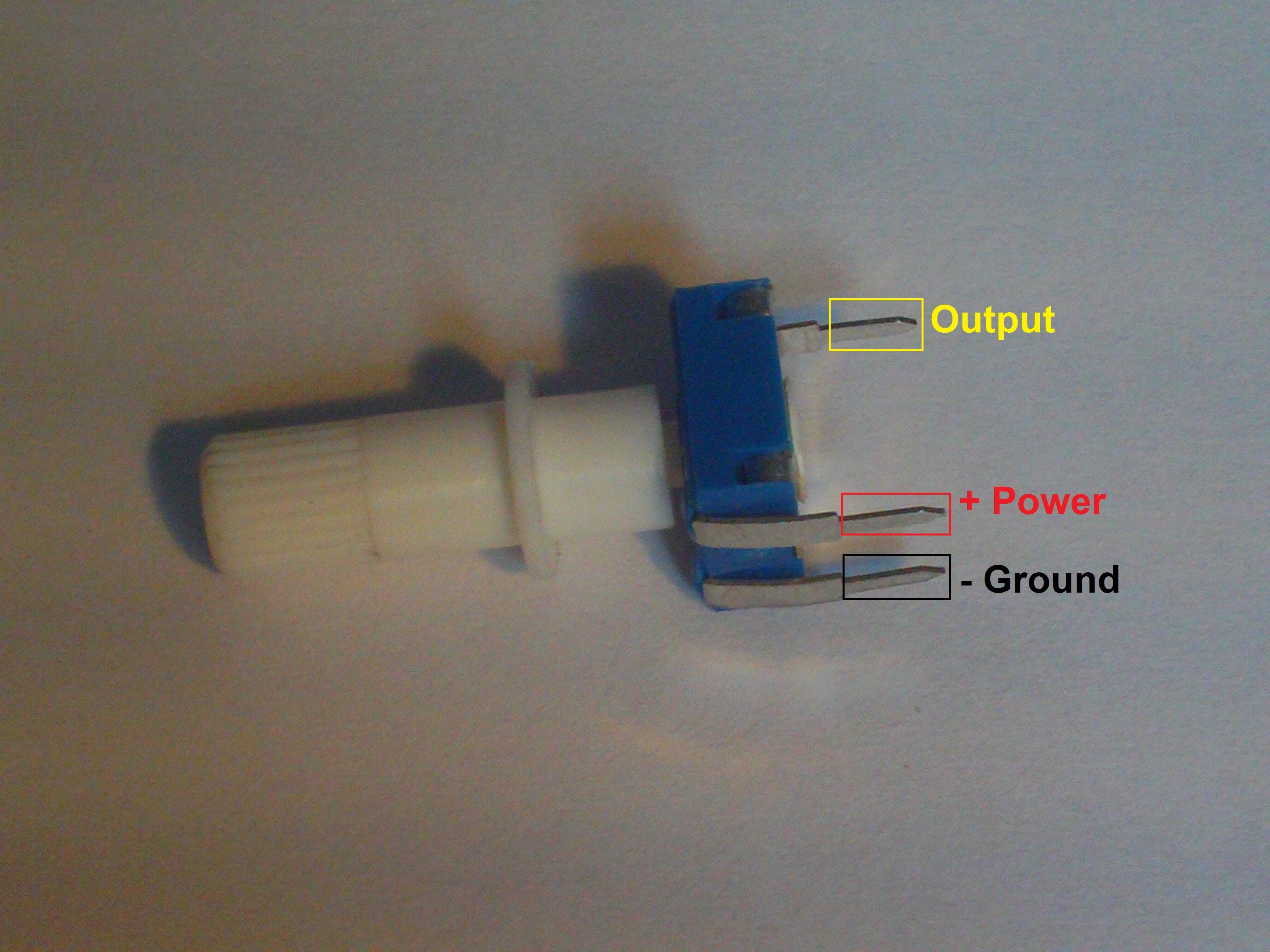
Note that most potentiometers have three terminals. One for input voltage (i.e. power), one for output voltage and one for ground. It’s important to know which one is the output terminal, but generally the ground and power terminals are interchangeable, however the arrangement of ground and power will dictate which way the potentiometer has to be turned/moved in order to increase/decrease the output.
In my case, if I wire the left leg to ground and the right leg to power my potentiometer will increase when turned clockwise and decrease when turned anticlockwise.
If I wire the right leg to the ground and the left leg to power then my potentiometer will decrease when turned clockwise and increase when turned anticlockwise.
For more information about potentiometers, there’s a quite substantial reference guide here on www.resistorguide.com.
Instructions - The Circuit:
Hopefully by now you’re getting used to setting things up and have already guessed that the first step is to get your breadboard ready.
In future tutorials I’ll be skipping that step in the instructions under the assumption that you’ve already done it. This is the last time I’m going to list breadboard placement as a fully fledged step.
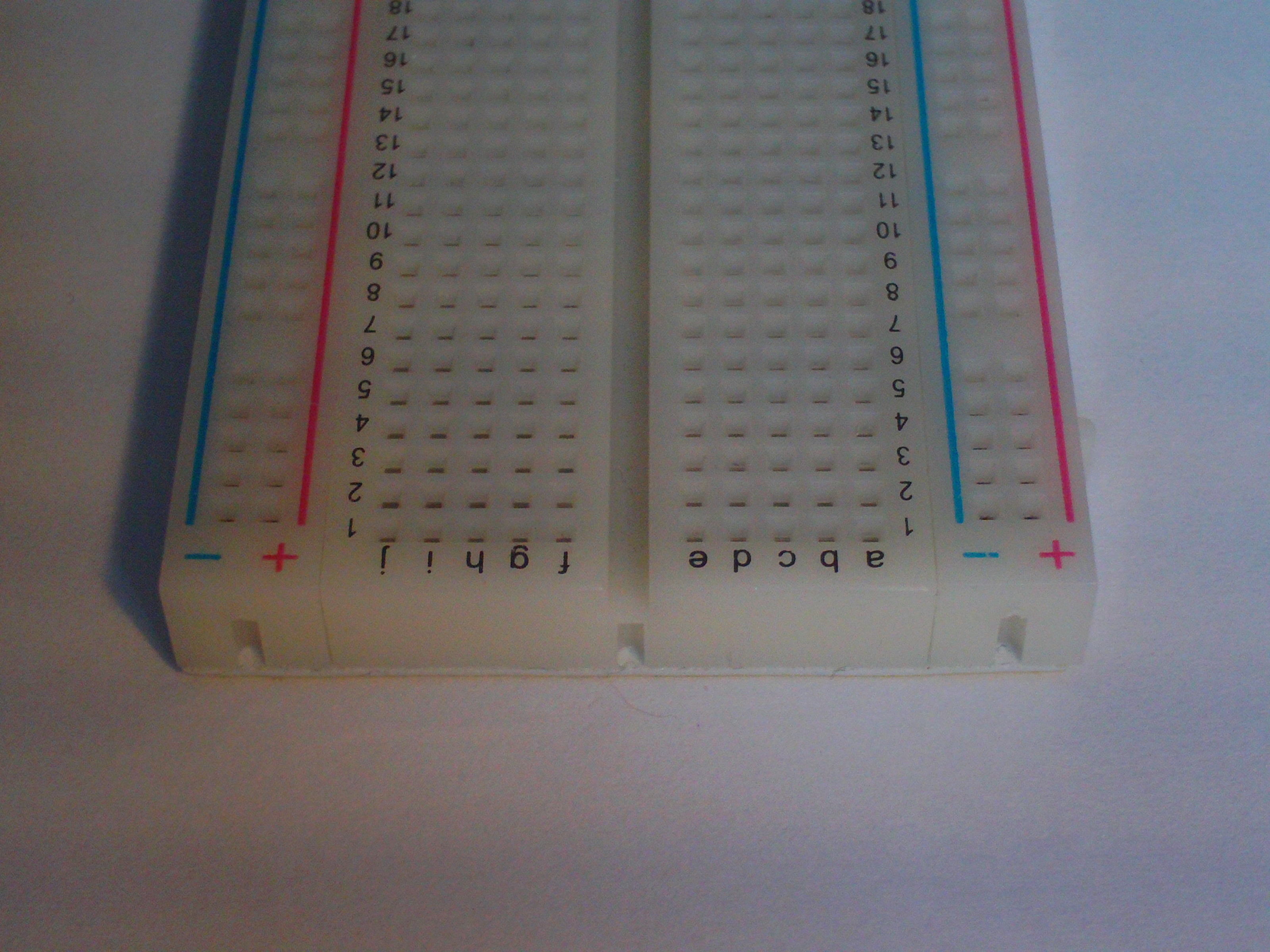
Step 1 - The Breadboard
Place your breadboard on a flat surface.
Step 2 - The Potentiometer
As mentioned earlier a potentiometer has three terminals: power, ground and output (with power and ground sometimes being interchangeable).
Make sure you know which is which for whatever kind of potentiometer you’re using.
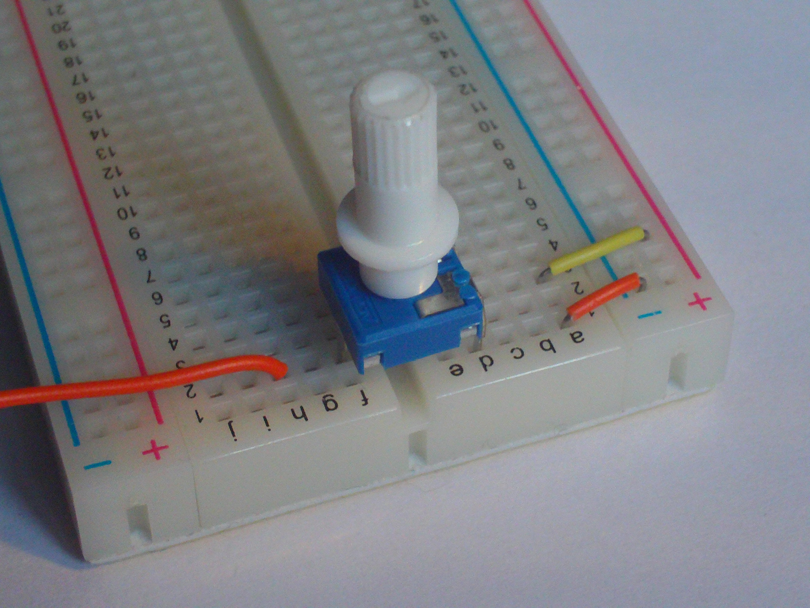
Then insert your potentiometer into the breadboard.
In my case my potentiometer has its legs on opposite sides so I’m going to be seating it across the two halves of the breadboard.
When you’ve got it placed, hook it up to the power and ground lines using some smaller wires.
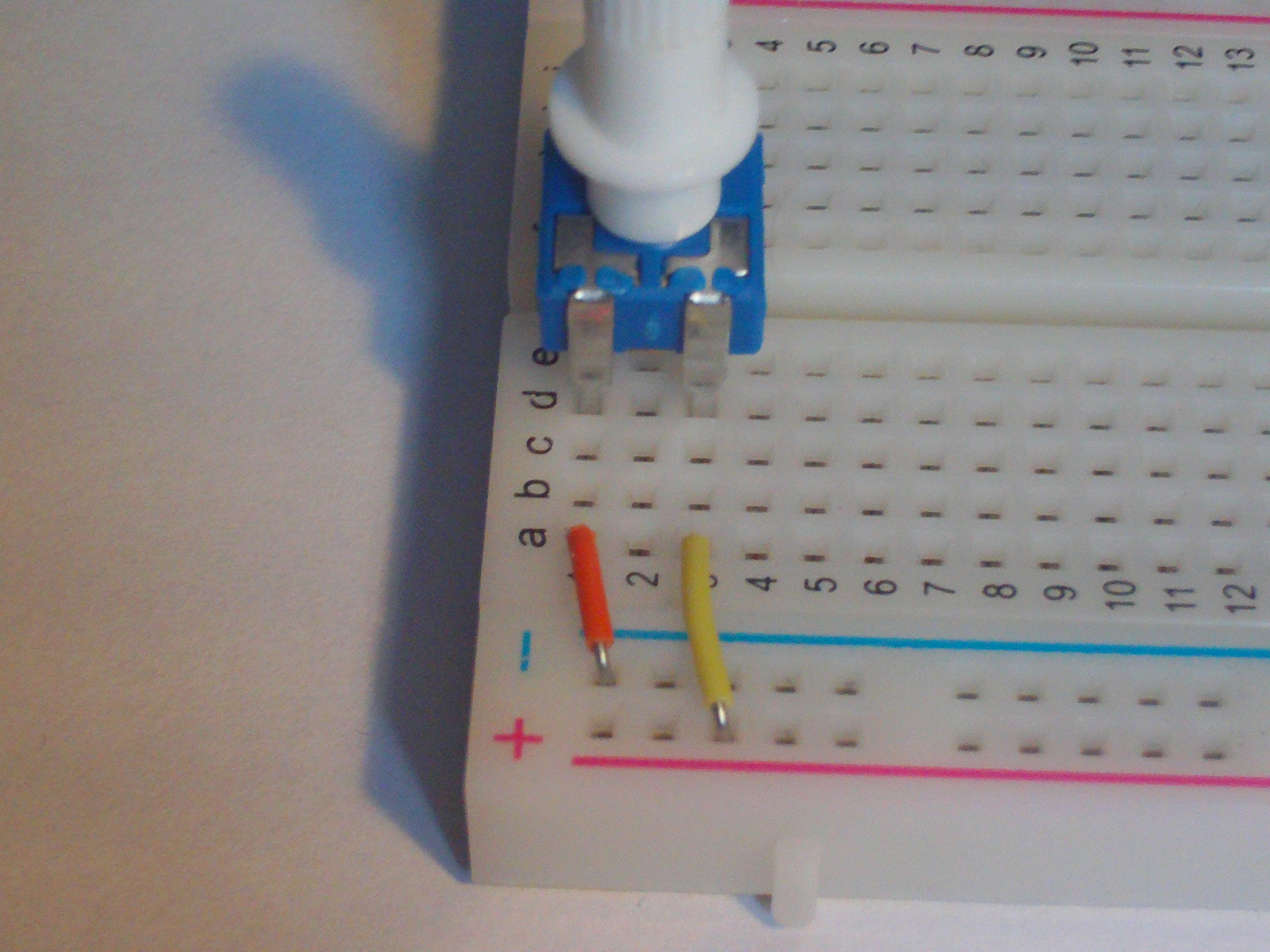
Then connect a long wire to the potentiometer’s output terminal. In my case the output terminal is at the back of the potentiometer.
Step 3 - The Pokitto
Now you need to hook up your Pokitto.
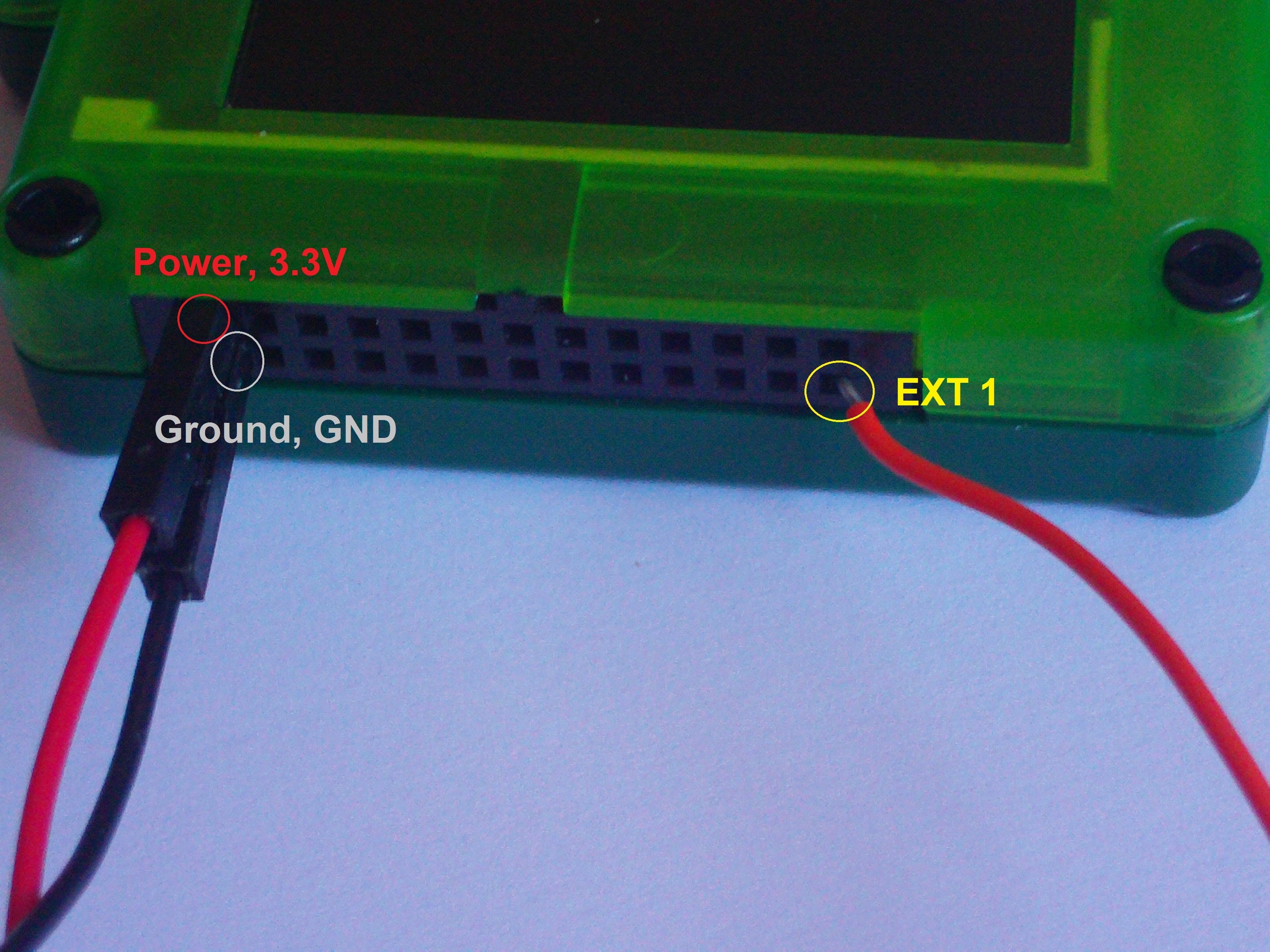
This is an input device, so like the button it’s going to need the Pokitto’s 3.3V pin connected to the power line on the board (indicated with a +) and the Pokitto’s ground pin connected to the ground line on the board (indicated with a -).
Like last time, the output needs to connect to a Pokitto pin. However, unlike a digital input (which can connect to any of the EXT pins), an analogue input can only be used on 4 of the EXT pins: EXT 1, EXT 2, EXT 3 and EXT 4. In this case I will be demonstrating with EXT 1.
A Note About Wire Colour:
You may notice that this time I am using a different set of wires for ground and power. As mentioned last time, the colour does not matter. However, these match the typical convention of a black wire being ground and a red wire being power. It’s good to be used to this convention and stick to it if possible.
I previously avoided using these wires because they are long and it’s hard to get them in frame when taking photos, but now that you are (hopefully) more used to the functioning of ground and power wires, it is less important for them to stay in frame.
Instructions - The Code
This time around the code is a bit more complicated because it has to adequately display a much more complicated input.
I won’t go too into detail about the code here because this tutorial is focusing on the circuit. However I hope to provide a supplementary tutorial about the code at a later date.
// Disable AVR/Arduino features
#define DISABLEAVRMIN

// The Pokitto library
#include "Pokitto.h"

// Required for std::sin, std::cos and M_PI
#include <cmath>

// Required for std::min
#include <algorithm>

// The pokitto core library
Pokitto::Core pokitto;

// Create an 'AnalogIn' object to represent the
// analogue input pin used to receive input from the potentiometer
// The object is set to use the EXT1 pin for input
AnalogIn thumbwheel0 = AnalogIn(EXT1);

// Create a Pi constant from the M_PI define
const float Pi = static_cast<float>(M_PI);

// The main function
int main()
{
	// Initialise the Pokitto
	pokitto.begin();

	// The main loop
	while (pokitto.isRunning())
	{
		// Update the Pokitto's state
		if (pokitto.update())
		{
			// Read the amount the potentiometer has been turned
			// as a percentage
			float value = thumbwheel0.read();

			// Calculate half of the screen width
			uint8_t halfWidth = pokitto.display.width / 2;

			// Calculate half of the screen height
			uint8_t halfHeight = pokitto.display.height / 2;

			// The circle radius will be the smaller dimension
			uint8_t radius = std::min(halfHeight, halfWidth);

			// Set colour to white
			pokitto.display.setColor(1);

			// Draw a filled circle in the centre of the screen
			pokitto.display.fillCircle(halfWidth, halfHeight, radius);

			// Set the colour to black
			pokitto.display.setColor(0);

			// Draw a filled rectangle over the bottom half of the screen
			pokitto.display.fillRectangle(0, halfHeight, pokitto.display.width, halfHeight);

			// Calculate angle of line
			float angle = value * Pi;

			// Get the x and y coordinates of the end point of the line
			int16_t x = static_cast<int16_t>(std::cos(angle) * radius);
			int16_t y = static_cast<int16_t>(std::sin(angle) * radius);

			// Change the colour to magenta
			pokitto.display.setColor(2);

			// Draw the line from the centre of the screen to the calculated end point
			pokitto.display.drawLine(halfWidth, halfHeight, halfWidth - x, halfHeight - y);
		}
	}

	return 0;
}
Explaining The Code:
Much like there exits a DigitalIn class for digital inputs, there also exists an AnalogIn class for analogue inputs. Given the similarity to both previous cases, it shouldn’t be too hard to understand the creation of the AnalogIn object.
I’ve chosen to name my object thumbwheel0 instead of potentiometer0 because thumbwheel0 is somewhat harder to accidentally misspell.
AnalogIn thumbwheel0 = AnalogIn(EXT1);
Much like DigitalIn there is a function for reading the potentiometer’s input using AnalogIn.
However, the returned value is somewhat different.
Because digital inputs only need to read a value of 1 or 0, digital inputs can use an integer type to return the result.
Analogue inputs on the other hand can represent a wide range of values, hence the mbed library (as used by the Pokitto) uses the computer equivalent of ‘real’ numbers (numbers with a decimal point).
Thus the return value of AnalogIn's read function is a value between 0.0 and 1.0 (including both 0.0 and 1.0). For example, if the potentiometer had been turned half way between its two stopping points then the return value would be roughly 0.5.
Part of the reason for the 0.0 to 1.0 range is because the values can act like a percentage. Multiply a value by 1.0 and you get 100% of that value, multiply a value by 0.50 and you get 50% of that value, multiply by 0.0 and you get 0% of that value (et cetera).
// Read the amount the potentiometer has been turned
// as a percentage
float value = thumbwheel0.read();
As for the rest of the code, the specifics are somewhat complex for this tutorial, but the gist of it is as thus:
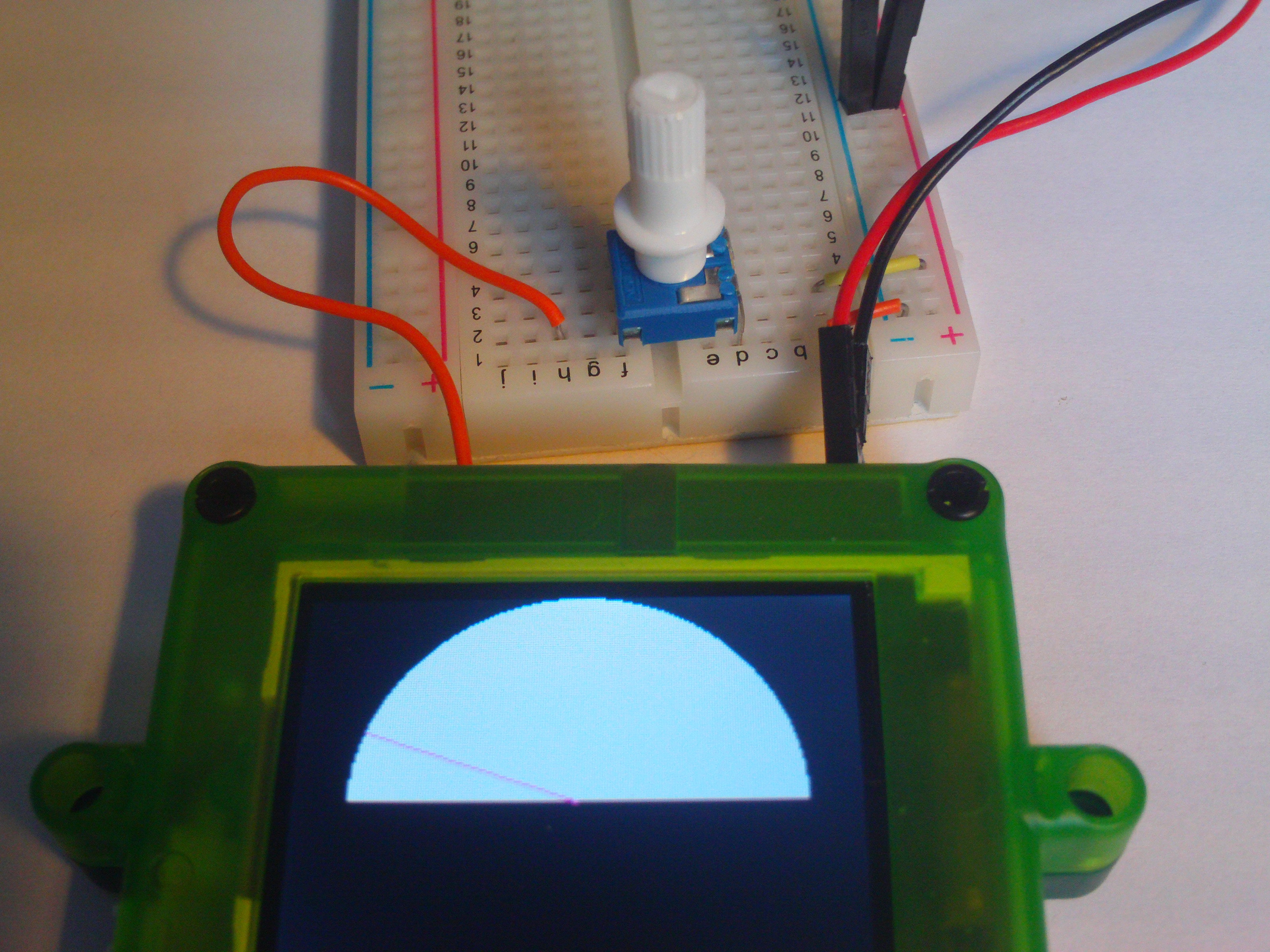
- A white circle is drawn in the centre of the screen.
- A black rectangle is drawn over the bottom half of the circle to make it look like a semi-circle.
- A magenta line is drawn from the centre of the screen to a point on the edge of the semi-circle calculated using the value read from the potentiometer.
A value of 0.0 leaves the line pointing to the left, a value of 1.0 leaves the line pointing to the right and a value of 0.5 leaves the line pointing up.
Hence slowly turning the potentiometer will slowly turn the line, like a needle on a dial.
What about the #define and #includes at the top?
For now, do not concern yourself with the meanings of #define DISABLEAVRMIN, #include <cmath> or #include <algorithm>.
All you need to know for the moment is that cmath is required for std::sin and std::cos to be used and that algorithm is required for std::min to be used.
The Result:
As usual, load the compiled code on the Pokitto and get ready to test.
If everything’s working correctly then you should be able to see the line moving as you adjust your potentiometer. The movement may not be entirely smooth, and loose connections can sometimes cause the line to jump around, but generally it should work alright and you should be able to see how the line moves.
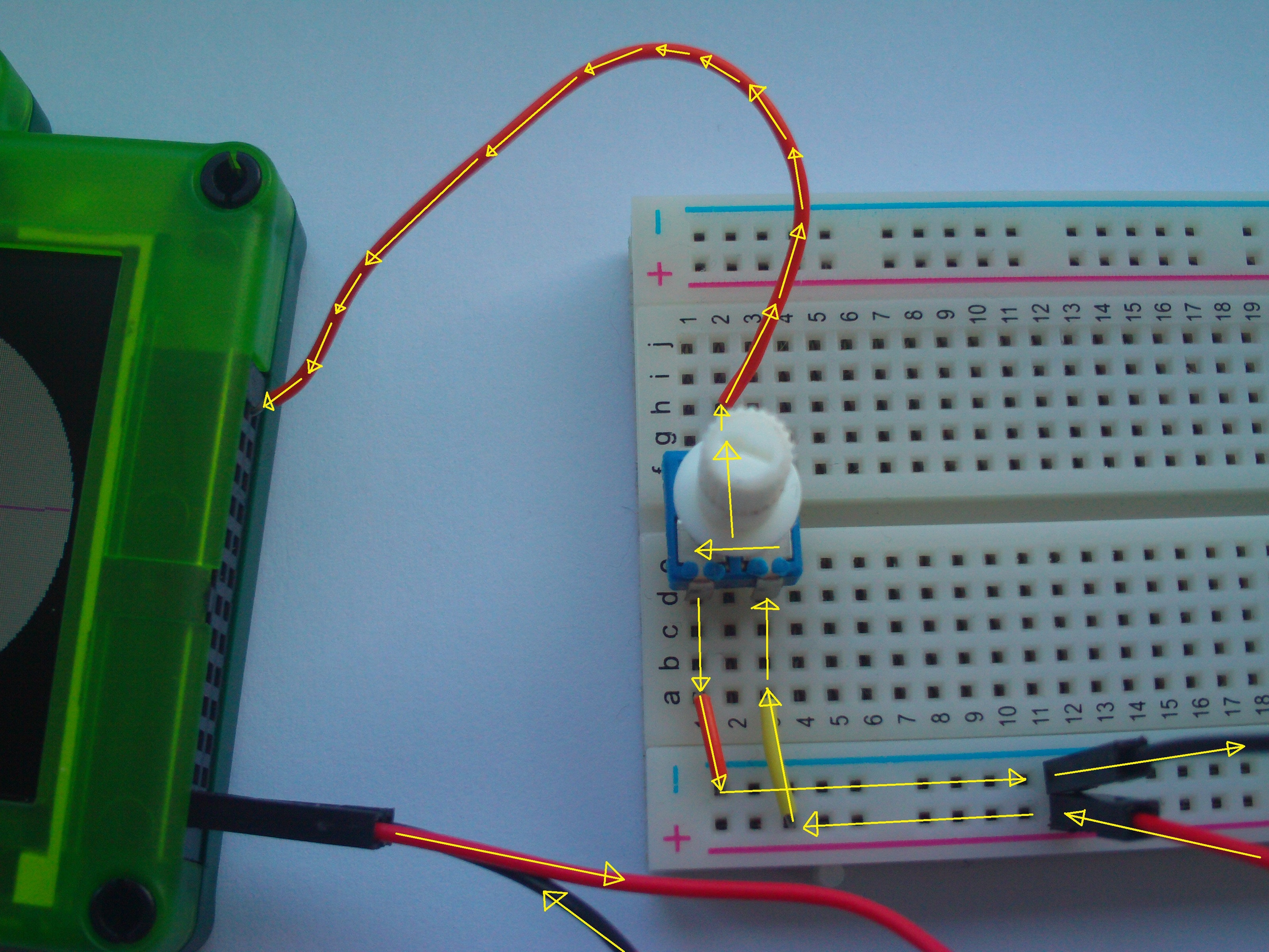
Lastly here’s an annotated photo to show you how the electricity is flowing. It’s fairly similar to how the digital button worked, with the exception that there’s an extra pin involved.
Do It Yourself Challenges:
Now that you’ve got a working circuit, why stop there?
Why not test how much you understood by having a go at these challenges?
(Note that not all of the information to complete these challenges can be found in this tutorial, you might have to read some others first and come back to the challenges.)
Code challenges:
- Change the code so that the potentiometer controls the size of a white circle drawn on the screen.
Code + Circuit challenges:
- Connect another potentiometer to a different input pin and print the values provided by each potentiometer using
pokitto.display.println - Connect a second potentiometer to the Pokitto. Use the two potentiometers to provide an x and a y value for the position of a shape (e.g. a circle) drawn on the screen.