Sure. Will add.
1 Like
J-link probes are great and SEGGER utilities also excellent, but depending on your location and various shipping costs, LPC-Link2 might work out cheaper. Its available from Embedded Artists in Sweden, and from several distributors (Digikey, Mouser, Farnell/Newark, Arrow, Avent, … etc). If you happen to have an LPC development board (like the LPC11U68 one Jonne has) you can actually flash it with J-link OB using the free LPCScrypt tool from NXP.
1 Like
Hi Brendon and thanks for the heads-up on LPC-Link2. Yes, buying an NXP dev board with integrated LPC-link2 is a very cost effective way of getting into hardware debugging. It also opens up the possibility to prototype mbed code on different kind of hardware. I highly recommend this approach.
I will try to put up a Pokitto-LPC-link2 hw debugging example also.
1 Like
HW debugging works with Segger J-Link  What I needed to do in addition to Jonne’s instructions, was
-
installing the J-Link SW from here: https://www.segger.com/downloads/jlink
I installed the “J-Link Software and Documentation Pack” (V6.22a). -
Start EmBitz. Update the correct “GDB Server path” in the GDB Server settings as described in Jonne’s Wiki (“C:\Program Files (x86)\SEGGER\JLink_V622a” in my case)
-
Then just connect Segger to Pokitto and PC
-
Rebuild and start debugger (F7). I did not have to change any build settings.
I have now just quickly tested HW debugging, but it looks to work much as debugging in Windows using Code Blocks.
3 Likes
How can I just flash any binary with Segger? I started Segger J-Flash application and seleted LPC11U68 as MCU. What else is needed to setup J-Flash or is that enough?
1 Like
That’s it. Nothing else is needed.
1 Like
J-Flash Lite worked. Thanks!
2 Likes
Which pins of the swd cable should i connect to what pins in Pex, if i want to use Pex for the hw debugging (and save poor Pokitto from cutting;-) ) ?
1 Like
Very easy: swd_clock, swd_io, reset and ground. Thats it
Swd = single wire debug. All data goes thru swd_io. Clock is clock signal, reset allows debugger to reset device, ground for common ground between debugger and device
2 Likes
Are you sure VCC is not connected? I could not get PEX to work with debugging.
Yep, I think VCC is needed also. VCC is used to detect if the device is “there” or not.
1 Like
Still no luck 
I have succesfully debugged through the PEX several times. I know it works.
I will next try some other GND pins in the segger SWD connector. Maybe they are no all really connected to the ground. SWO is not used, right?
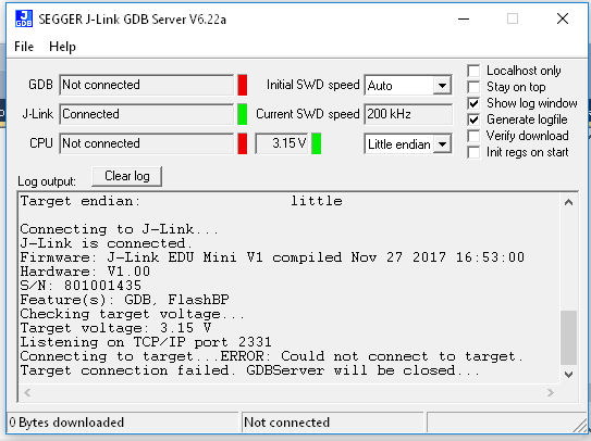
could you elaborate on how it fails? no device found?
Could not connect.
Switch swdio and swdclk around. Maybe they are wrong way around
Tried that but the same result
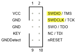
So I have connected:
SWD        PEX
====       ====
VCC--------3V3
SWDIO------SWD_IO
SWDCLK-----SWD_CLK
nRESET-----RESET
GND(P3)----GND
I have checked the connections with a multimeter.
Same result on both of your pokittos?
Yest, fails with the other (proto) Pokitto too. That was working before with on board SWD connector. I cannot test it now as I have ruined my SWD-to-SWD cable.