
Look at that beautiful piece.
Aha, I was right about the Game & Watch link!
The painting-like art style of those old screens is unmistakable.
And it was actually called Donkey Kong…
I was thinking it might have been called “Jumpman”,
because that’s what Mario was called (at one point) before he was Mario.

Looks almost perfect to me.
Pedometer hat, just a hat to collect steps, would have to have a button cell to work and when you launch its app you get its information and can save it to sd.
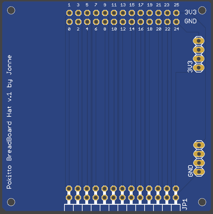
The ready product
PEX duplicated and chainable on top, 4 x GND and 4 x 3,3V available on the right side
Now, if only full schematics for the Pokitto itself were available.
How do you connect between the PEX and the breadboard, and chain hats at the same time?
If the board in the above post is the final layout, you’re using awfully thin traces for power and ground. You should have used a thick trace for power and flood filled for ground, or flood filled both on opposite sides.
@MLXXXp true on both counts. Last schematics of Pokitto will be latest in the next mag (june/july)
Traces need.to be thicker and flood filling also, I will fix that
My suggestion on how to do a breadboard hat:
It would be similar to @jonne’s current v.1 design but have pads for an additional 2 headers, which would probably make it a little longer.

In the above graphic, the circuit board is green and the components on it, from left to right, are:
- Right angle dual row 26 pin male header to plug into the PEX.
- Straight dual row 26 pin female header.
- Solderless breadboard (orange)
- Straight single row 4 pin female header for ground, in front of the breadboard, as on the current version.
- Straight single row 4 pin female header for 3.3V, in front of the breadboard, as on the current version.
- Straight dual row 26 pin female header.
- Right angle dual row 26 pin female header to chain another hat.
Here is how the board would be wired. (Only the highest numbered 6 pins of each 26 pin header are shown.)
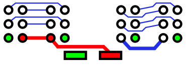
The left hand straight header is wired 1 to 1 with the male right angle header. This header is for jumper wires to connect to the breadboard or to the other 26 pin straight header. 3.3V power, shown in red, is also wired to the 4 pin 3.3V header (shown as a red rectangle). Circuit ground, shown in green, is connected to all the 26 pin headers and the 4 pin ground header (shown as a green rectangle), using a flood filled ground plane.
The ground plane could be on only one or both sides of the board. If only one side is used for ground, the other side could optionally be used for a 3.3v power plane (but personally, I’d be worried about having a large powered area on the board, even if it’s covered by a solder mask). All 3.3V power traces should be made as wide as there is room for. It’s also possible to make this as a single sided board (and swapping the positions of the 4 pin headers makes it even easier).
The right hand straight header is wired 1 to 1 to the right angle female chaining header but these aren’t wired to anything else, except for the ground pins. I you want to connect to a pin on the chaining header it has to be jumpered between the straight headers or from the breadboard or the power headers. This allows for inserting circuitry between a chained hat and the Pokitto’s PEX. It also allows for re-arranging pin positions between the Pokkitto’s PEX and the chaining connector. (An example of doing both these things is for FM radio hat experiments, where there’s been discussions about adding op-amps on the outputs and also using different PEX pins.
Even 3.3V power isn’t connected to the chaining headers. This allows measuring the current draw of a hat by inserting an ammeter in series. It also allows powering a hat from a separate power source.
For a lower cost version of the breadboard hat, without hat chaining ability, the two isolated 26 pin headers could be left unpopulated.
One thing I’m wondering when looking at the photo of the current circuit board:
Are the PEX pins really numbered starting from 0? I can’t recall ever seeing a header, connector, socket or IC that doesn’t number the pins starting from 1.
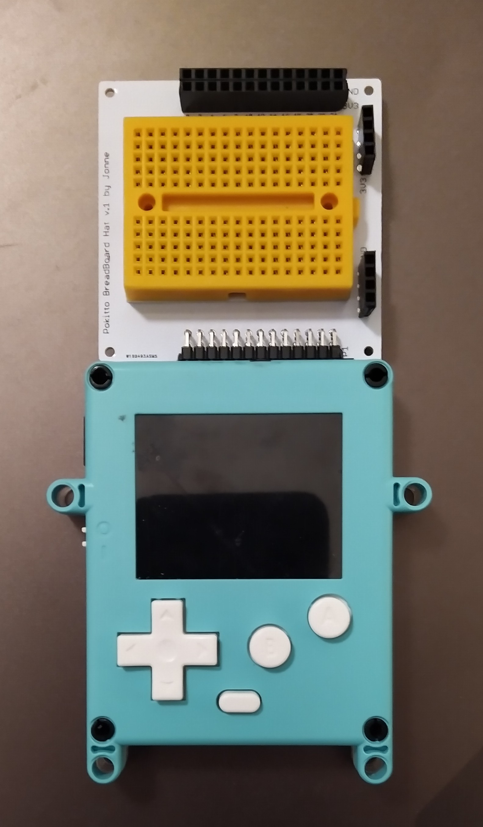
Referring to the completed breadboard hat photo:
I would have stuck the breadboard down rotated 180 degrees. That way another breadboard could be joined to it on the left side using the now exposed connecting tab.
Also, @jonne, if you do another revision of the board (hopefully following my design above), you may wish to add holes that line up with the two mounting holes on the breadboard, in case someone wants something mechanically stronger than double sided foam tape. It appears that the same hole spacing is used for all of this size breadboard. (However, the size of the dovetail connectors on the sides isn’t consistent. I have almost identical breadboards from 3 different manufacturers that each have different size, incompatible, dovetails.)
Hey, I appreciate the feedback. Now is my turn: how about you make a new revision? Without sounding rude, you’ve been here quite a while and obviously have all the requisite skills. I will try to oblige, but your experience would be even more valuable in the form of files.
Here are the eagle project and board files:
bbhat.zip (16.4 KB)
I can put it on the queue but you’ll be waiting months if not years by the time I get to it. Personally, I’m not even interested in a breadboard hat but since others seem to be enthusiastic about it, I thought my feedback might be appreciated.
It is appreciated. I just have the same kind of a queue.
I don’t mean to be a pest, but was there any more movement on the BreadBoard hat  ?
?