I have no idea how to compile the US version I know it is a lot to ask but can you instruct me how to do it? unless you have it already compiled.
There is a precompiled binary (Cyclometer-US.bin) in the zip file I provided.
Here: Cyclometer-US.zip
It’s got wheel circumference changed to 2153 mm if that’s closer to what you have. I can of course compile another one if that’s not correct.
Or if you want to compile it yourself, in FemtoIDE just choose ‘Build’ from Build menu or hit control-b. It will create Cyclometer.bin in the project’s folder.
1 Like
Thank you! I’ll dl it and install it on pokitto tomorrow.
Finally got to install it, it is nice, Thank you, I just need to make my “sensor” and mount it, went out for a short ride the other day, (down the road and back) and there are a lot of recreational cyclists who ride my road one hollered (yes Im southern lol) and we stoped and talked a bit he showed me how to best adjust my brakes, assured me that I could change out the stem on it then commented that his brand new bike was several pounds heavier,
soon as my project box gets here I can finish the “dashboard” for the Cylon eye on front and yes Im Liberating the pegs from my sons lego box to mount Pokitto.
2 Likes
not sure what I’ve done bt it doesn’t seem to be reacting to the magnet
I tested the switch with a simple led and it works, but the pokitto doesn’t seem to see it

I get the feeling that one on the bike in the pic is actually a Hall effect senso and not a reed switch 
And the Hall effects I ordered have not shipped yet
That looks like a reed switch in the picture. If you have connected it correctly between 3V3 and EXT0 pins on Pokitto, then I have no idea what could be the problem. I tested the Cyclometer US version binary and it works for me.

You could try replacing the reed switch with a manual switch or just a wire that you connect and disconnect by hand, but clearly your picture shows that the reed switch is working.
1 Like
Tried a momentary button, but nothing happened as I pressed it, I even used two jumpers and just tapped them together. I bet mine mah have something wrong with it. lol
@jonne get me another pokitto ready lol. White back and buttons transparent pink front. When tax refund is issued I’ll need another probably.
2 Likes
I would try editing and re-compiling the code to use a different input, and wire the switch to this new input. If it works, then the original input is likely bad. If it still doesn’t work then it’s probably that you’re wiring it wrong.
I have no idea how to compile the code unfortunately, I believe it may be my pokitto I need to test it to see it the header is good
I’m getting 3.2 volts on the pin and .31 when it’s wired up for the sensor.
I tried setting the polarity one way them the other but nuthing.
Also tried the metric version and got no response with it either.
The program sets an internal pull-down resistor on the EXT0 pin, so you should normally get 0 volts, and 3.2 volts only when the reed switch is connected and you bring magnet next to it.
I tried to make a version that uses other pins as input but strangely it didn’t work. The pull-down resistors seem to be activated correctly but my program receives no interrupts from pins other than EXT0.
It’s probably my pokitto
Let me take a look at this and get back to you
It is highly unlikely, that a single pin is not working on an otherwise functional pokitto - though it is possible
1 Like
To verify the hardware, it would be best to have a simple program that sets a pin to input mode with pulldown and then polls it continually and outputs its state to the display. You could do this for more than one, or all, the PEX inputs at the same time.
Anything you need me to do?
Wait patiently. I was kinda busy. I will get back to this soon
1 Like
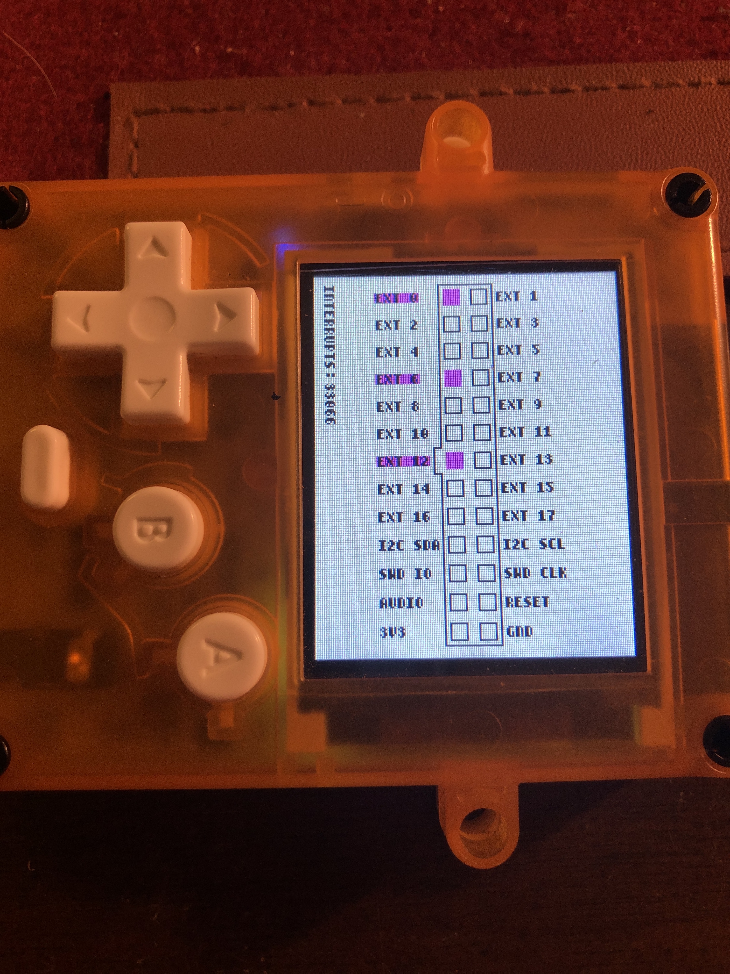
Here is a program to test EXT0-17 pins in the PEX header. It enables pull-down resistors and attaches interrupt handler to all EXT pins. The program displays total number of detected interrupts and shows pin states by highlighting pins with ‘high’ state.
Binary: ExtTester.bin (53.3 KB)
Source: ExtTester.zip (4.7 KB)
This is what it shows for my Pokitto:
        Input   IRQ
EXT0    +       +
EXT1    -       -
EXT2    -       -
EXT3    +       +
EXT4    +       +
EXT5    +       +
EXT6    +       +
EXT7    +       +
EXT8    +       -
EXT9    +       -
EXT10   +       -
EXT11   +       -
EXT12   +       -
EXT13   +       -
EXT14   +       -
EXT15   +       -
EXT16   +       -
EXT17   +       -
So I got interrupts from EXT0 and EXT3-7.
EXT1 and EXT2 didn’t function as input at all.
5 Likes
I think the following from the documentation can answer some part of the issue (https://www.nxp.com/docs/en/data-sheet/LPC11U6X.pdf):
8.11 Pin interrupt/pattern match engine
The pin interrupt block configures up to eight pins from all digital pins for providing eight
external interrupts connected to the NVIC.
The pattern match engine can be used, in conjunction with software, to create complex
state machines based on pin inputs.
Any digital pin except pins PIO2_8 and PIO2_23 can be configured through the SYSCON
block as input to the pin interrupt or pattern match engine. The registers that control the
pin interrupt or pattern match engine are on the IO+ bus for fast single-cycle access.
If I understand well, that means you might not receive interrupts for more than 8 pins - which seems consistent about why EXT_8-17 aren’t receiving IRQ.
I tested the bin, I got the same input issue about EXT1 and EXT2, but also EXT16. Everything else behave as intended.
Here is a screen shot of mine
I need to try a switch on it right
tried it with a switch and it didn’t register any interrupts with the magnet passed over it, I took it apart and cleaned it and checked the pins they are kinda rough but solid so that shouldn’t be the issue,
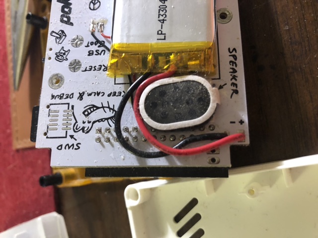
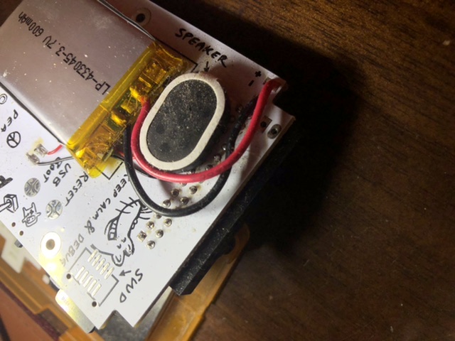
The pins in case anyone wants to see them,
Only three pins functioning as inputs? At least EXT0 is among those three, so to my understanding the cyclometer should work.
I now tested also my newer Pokitto and it is not getting input from EXT16, although it worked on the old one.
You are right. If I skip EXT0-7 and enable the rest, then I get interrupts from EXT8-15.
I wonder why the cyclometer seemed to be receiving interrupts only from EXT0? It handles both rising and falling edge, so I guess it’s using 2 (of the 8 available) IRQs per pin. Probably I first added EXT1 and EXT2, then maybe EXT16 and EXT17 from the other end. Thats already wasting all remaining 6 IRQs on pins (EXT1, EXT2, EXT16) from which I didn’t get input anyway.