Arduboy owners. Help please!
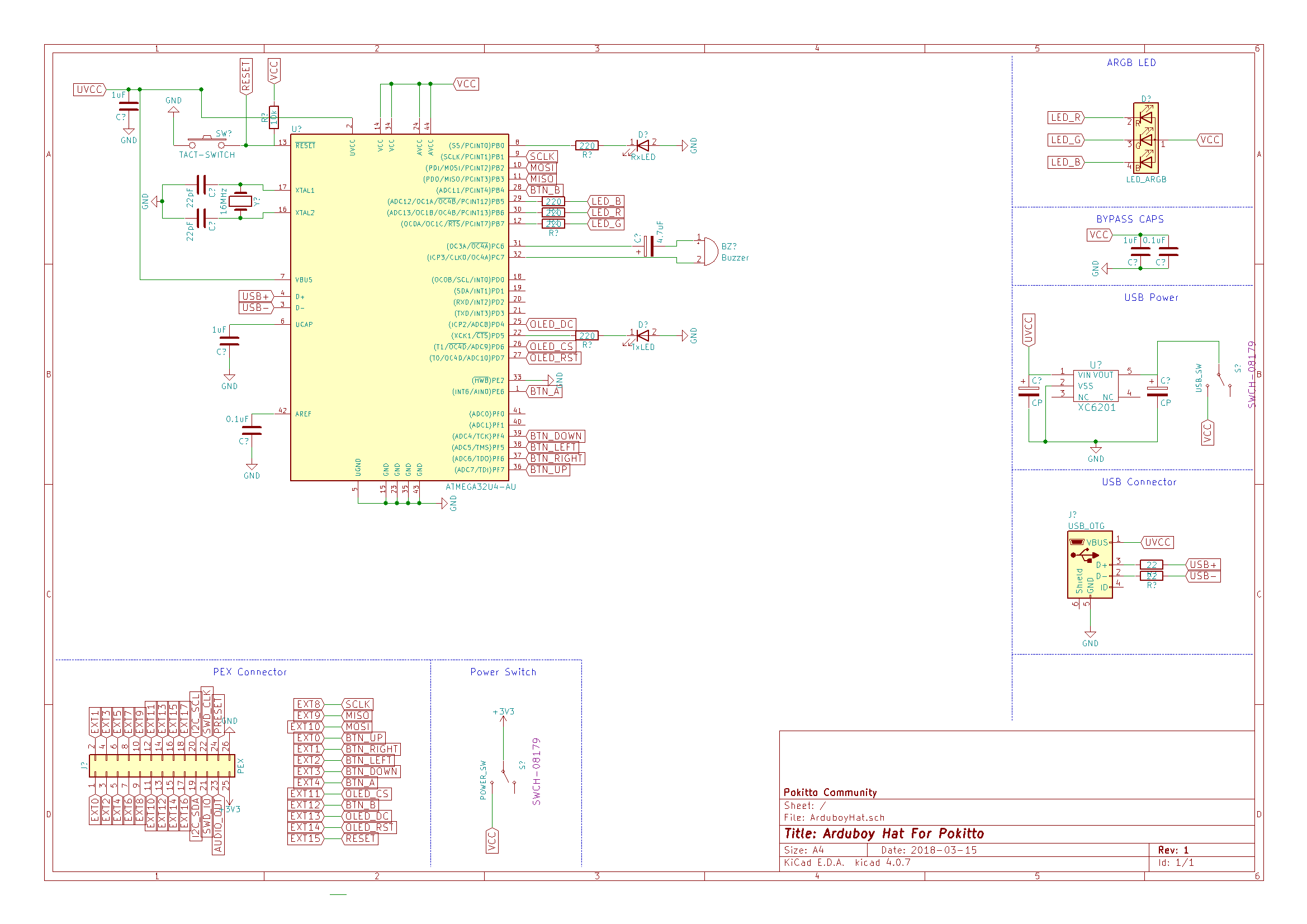
I started working on PCB. I found a schematic of arduboy (page says it’s production schematic). But…
It’s working completely on battery voltage and crystal is 16MHz. There are no boost circuit. Running atmega32u4 with battery is not a good idea (lipo batteries can go below 3v and below 4.5v running at 16MHz is not safe).
Pokitto is 3.3v device. We need boost converter, logic level shifters etc. for this.
Is any arduboy owner faced any problem due overclocking? I want to stay in safe side but for lower production cost we can do overclocking.
This was discussed back in the design stages (literally years ago now - time flies!!) and Kevin acknowledged this, and said running it outside of the specifications would be no big deal:
Thanks for information
We can try running at 3.3v and 16MHz for a while and see what happens. If we see any problem I can add other circuits. @Hanski production cost is not too much. When I draw a schematic I can say what is the production cost. Also you’re right. We need to split this discussion to another post.
Edit 2: Added PCB layout images. I will add RGB led later. Board dimensions are 49x32mm. With this dimensions we can use seeed or jlcpcb PCB service with 2x3 panelled boards. It means you can buy 60 boards with just 5 dollar (plus shipping ). Also small pcb means cheaper oshpark boards. I will calculate cost of one populated PCB tomorrow.
To be safe, you should connect PD2/RXD and PD3/TXD to UART capable pins on the PEX, in case we want to use a serial based bootloader on the hat, as discussed above:
@MLXXXp
Oops… I forget that. Thanks
I see your posts on Arduboy forum. Your suggestions are really great to make stable hardware. If you want to say something about this project, I glad to hear your suggestions.
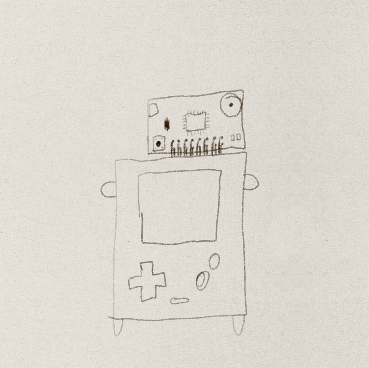
Wonderful work! I suppose the PEX male connector in PCB will finally be facing downwards. As the PEX female connector in Pokitto is not in the middle of the device, should the PEX male connector be also more near the right edge on the PCB? To make it to look symmetric when connected.
I tried to align right corners in this version of PCB. I can draw PCB as wide as Pokitto or with same wideness i can relocate pins to look like it’s in the middle of pokitto.
Actually, it could be more pocketable, if you design the PCB to be full width of Pokitto (leave some millimeters for the case), and can reduce the height of the PCB.
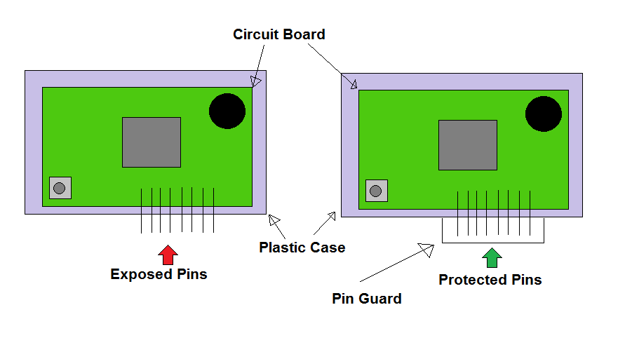
Alternatively if that’s difficult, perhaps provide a pin guard so that the hat can be removed and then protected when put away (e.g. in a pocket).
(Actually that’s a good idea either way.)
Though I agree that making it stretch the whole length would make it easier to work with/handle. It would also hopefully mean that the weight would hopefully be distributed more evenly, putting less stress on the pins.
@Hanski You’re right. I will work on it today @Pharap I couldn’t catch your idea
Here is another question. Is USB needed for Arduboy Hat? Removing USB connector makes everything easy and simple.
Basically, the hat has male pins that plug into the PEX, and male pins are likely to get bent,
so creating some kind of guard to protect the pins would allow people to safely put the hat in their pocket.
It depends. Some Arduboy sketches use the USB port to emulate a keyboard, mouse or game controller. Some use it to mirror the screen to capture video or screen shots. Some developers use it to send debug messages to a serial monitor.
If powering () though USB is not necessary I will split USB VCC line and atmega VCC line. USB peripherals are still usable but atmega cannot power through USB VCC line. With this setup we can throw some parts like voltage regulator and some tantalum caps. It makes board cheaper and easy to find necessary parts.

 - time flies!!) and Kevin acknowledged this, and said running it outside of the specifications would be no big deal:

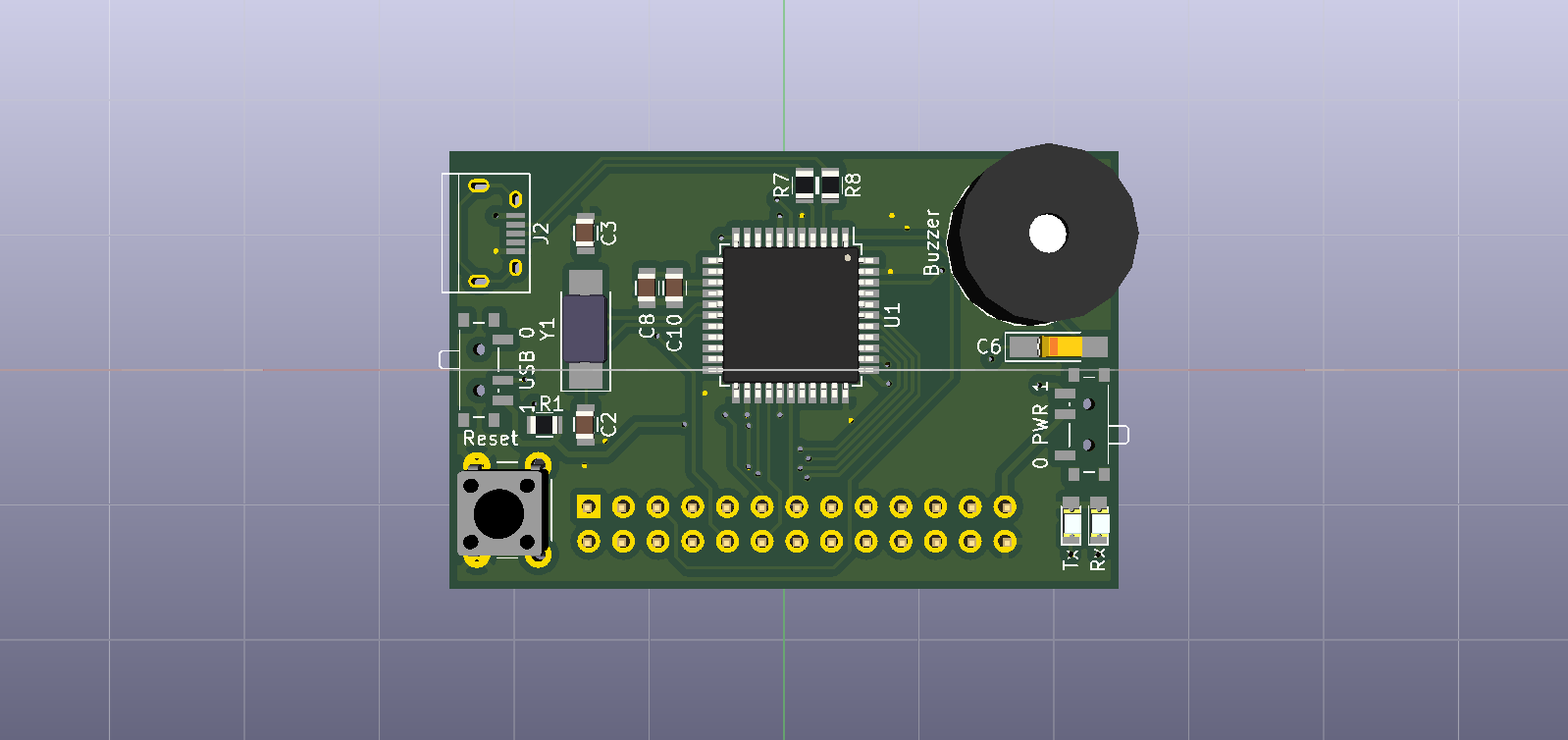

 ). Also small pcb means cheaper oshpark boards. I will calculate cost of one populated PCB tomorrow.


 ) though USB is not necessary I will split USB VCC line and atmega VCC line. USB peripherals are still usable but atmega cannot power through USB VCC line. With this setup we can throw some parts like voltage regulator and some tantalum caps. It makes board cheaper and easy to find necessary parts.