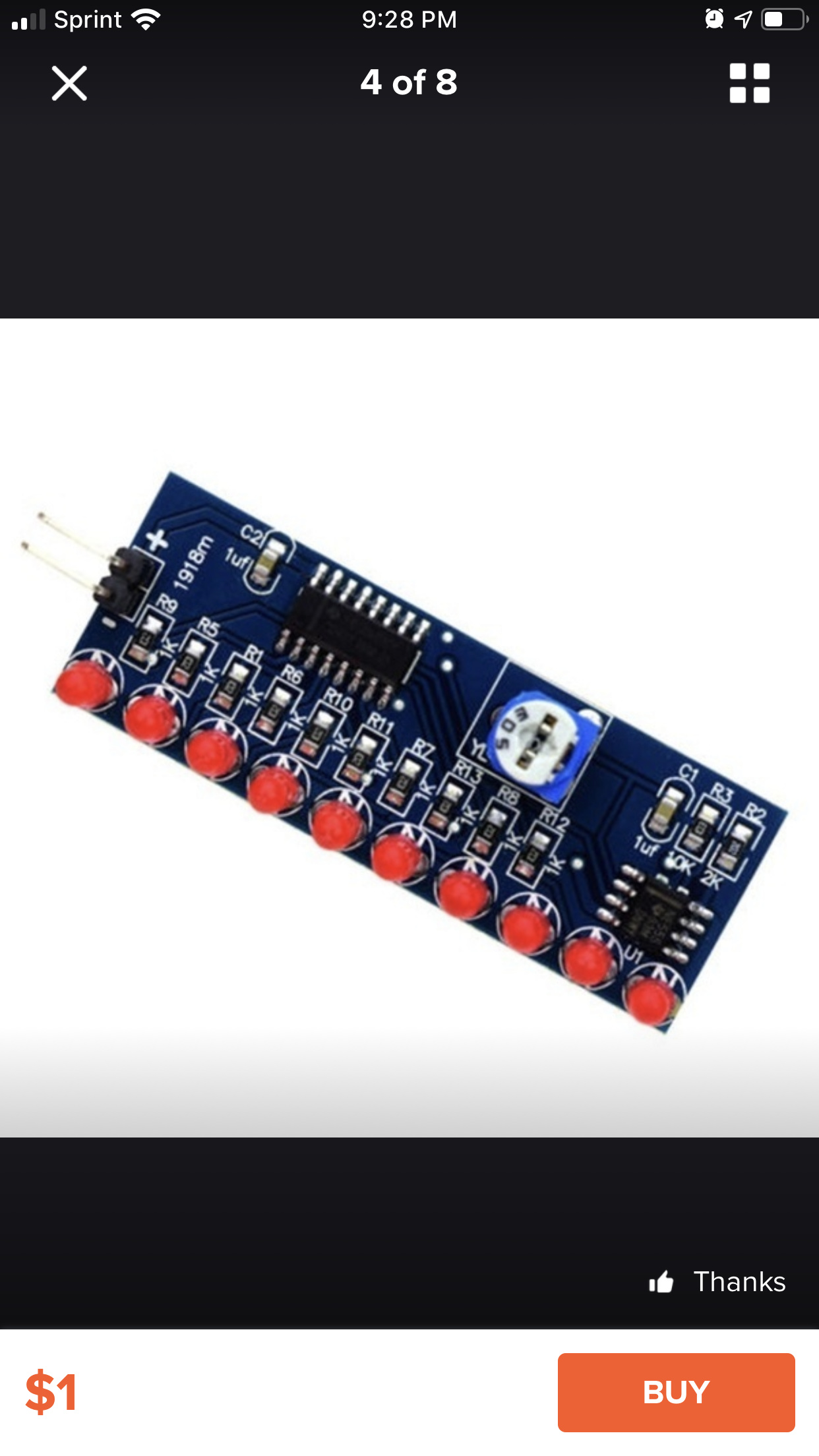
And I’m a little intimidated, I didn’t realize that it was full of little tiny surface mounted resistors and both chips are surface mounted, and I need a new tip for my iron, it only has a medium tip for through hole stuff, and it is way too big.
So to cut to the point, any tips for putting this thing together? And I’m not even sure of the voltage, I’m going to presume it’s 5 or 3
Edit, it’s 2-5 - 12 volt and I think it’s a Larsen scanner (KITT eye or a cylon eye)
Surface mount components require you to be a bit more strategic before you solder.
plan ahead in which order you solder the components, starting from the resistors (you can not reach them from the outside if other components are in the way)
you need tweezers
in high probability, you need solder wick (a metal braid for sucking up excess solder) as well. Biggest problem in surface mount is accidentally putting too much solder. If you put too much solder, you can get a solder “bridge” between the legs of a chip and solder wick is the only tool you can really use to fix the situation
so 1. plan order of soldering 2. get tweezers 3. solder wick recommended 4. be careful to use as little solder as you can (just a bit on the pads/solder tip) because too much solder is hard to fix
That said I personally solder most smd components with a hot air station, not a soldering iron
Well not really lol. The large chip a ti 18dn6wy cd4017bmseems to be the problem, when I press on it it they work better but 9 and 10 don’t.
After tweaking it a bit, d6 doesn’t work, I get a reading at the resistor, but none at the led, and the led will glow when tested, so there is something else wrong, not a problem lol it works mostly but not as I thought it would, I thought it was a Larsen scanner, and it only travels one direction. On a happier note
I think I recognise that voice, but I can’t place it.
It sounds a bit like Jeremy Clarkson, but less nasally and not as deep.
I know precisely what “ineptitude inside a brewery” is referring to though.
An excellent idiom.
Apparently a child friendly alternative is “couldn’t organise a bun fight in a bakery” (which sounds rather fun).
I’ve never heard anyone actually use that alternative,
but maybe that’s just indicative of the company I keep.
Another version is “couldn’t run a whelk stall”,
but that’s so obscure that probably only cockney OAPs would understand it.
For what it’s worth, your soldering doesn’t look too bad,
there seems to be only minor spillage and a few small gaps here and there,
but I’m hardly an expert on soldering so my opinion on that probably isn’t worth much.
James May, watching James May’s man lab in the background lol.
The multimeter registers a reading when I check from the resistor to the chip, so it’s who knows what is wrong but like I said I had fun.
I just realised it’s supposed to be a video.
The video isn’t playing properly for me, so I thought it was just a random bit of audio.
If anyone else is having problems, here’s a .webm:
(As an added bonus, this .webm is only 342KB versus the original .mov's 8652KB. That’s approximately 25 times smaller.)
That explains why I was thinking Jeremy Clarkson.
I never watched Top Gear so I’m not very good at telling the trio apart.
In a twist of irony, apparently the 5th episode of the 3rd series of ‘Man Lab’ featured ‘Rory Barker’ (whoever that is) running a whelk stall, so maybe I was a bit premature with the cockney OAP cliché. :P
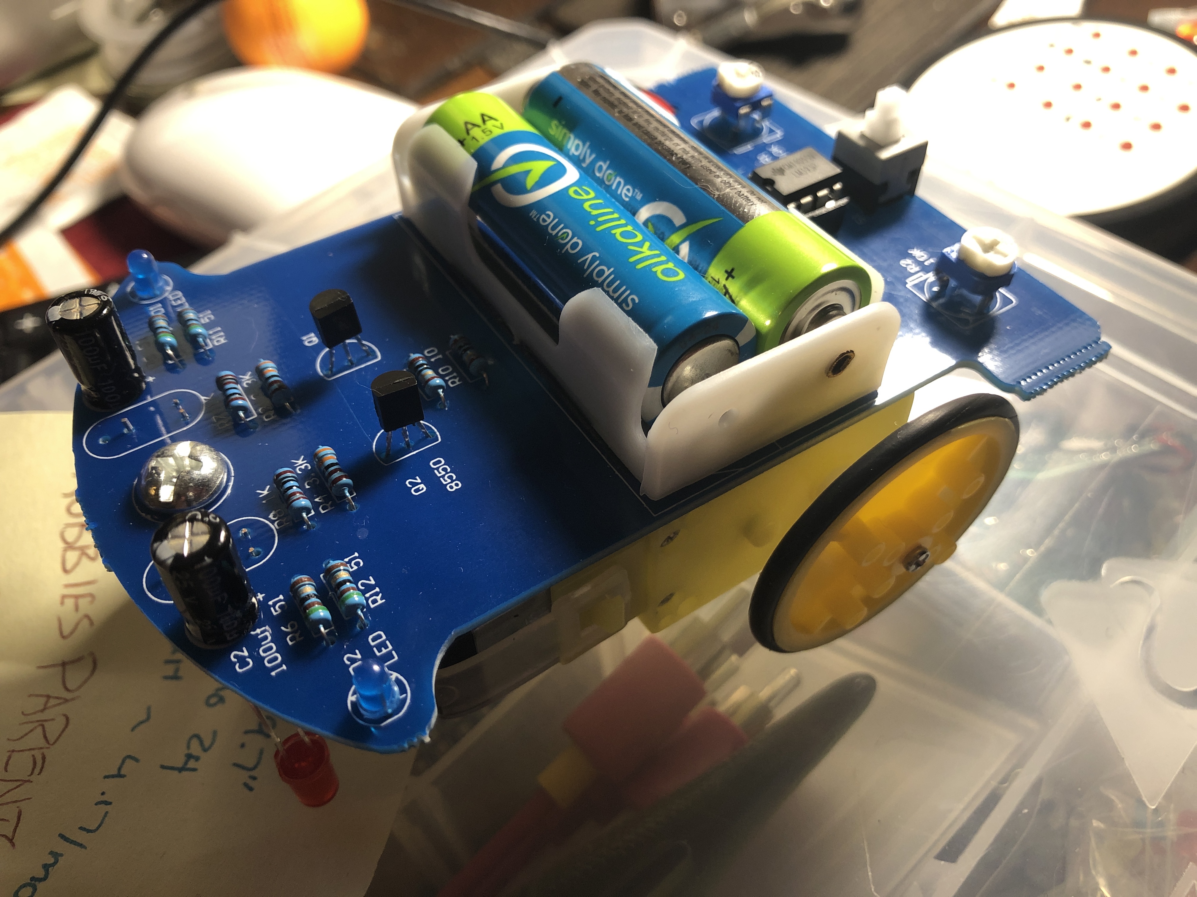
Well the little car is sorta broke, one of the red leds Broke free when Robbie was playing with it and the trace on the board broke. Still works otherwise I will probably put a different led on it to light up from one
Just a question, I have several of those solar garden lights that have dead batteries, I considered taking them apart and scavenging the sensors and the solar cells from them, to make a solar charger am I correct to presume I need some sort of control to regulate the power it supplies.
With most of the recent ones I’ve looked at, the solar cell is the sensor. There’s just the solar cell, LED, control chip, a few resistors and/or capacitors, a power switch and the battery.
Yes. The voltage provided by a solar cell will vary depending on the amount of light it receives and the amount of current the load draws from it.
Unless you’re planning to use a very large number of cells recovered from garden lights, you would probably be best to use a low power energy harvesting circuit. For example:
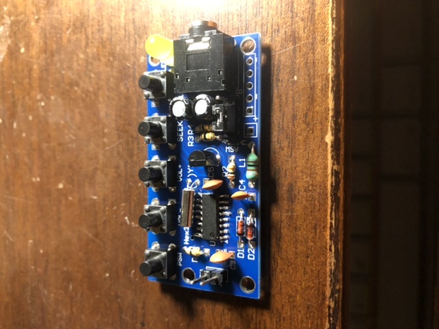
Well new kit came from wish, a fm radio, it had a surface mount chip, pain to solder but I did a bit better just need a better iron.
It works and plays really well, I’m going to mount it in that amplified speaker I built and I did modify it with a header pin for power rather than use the aa battery box it came with.
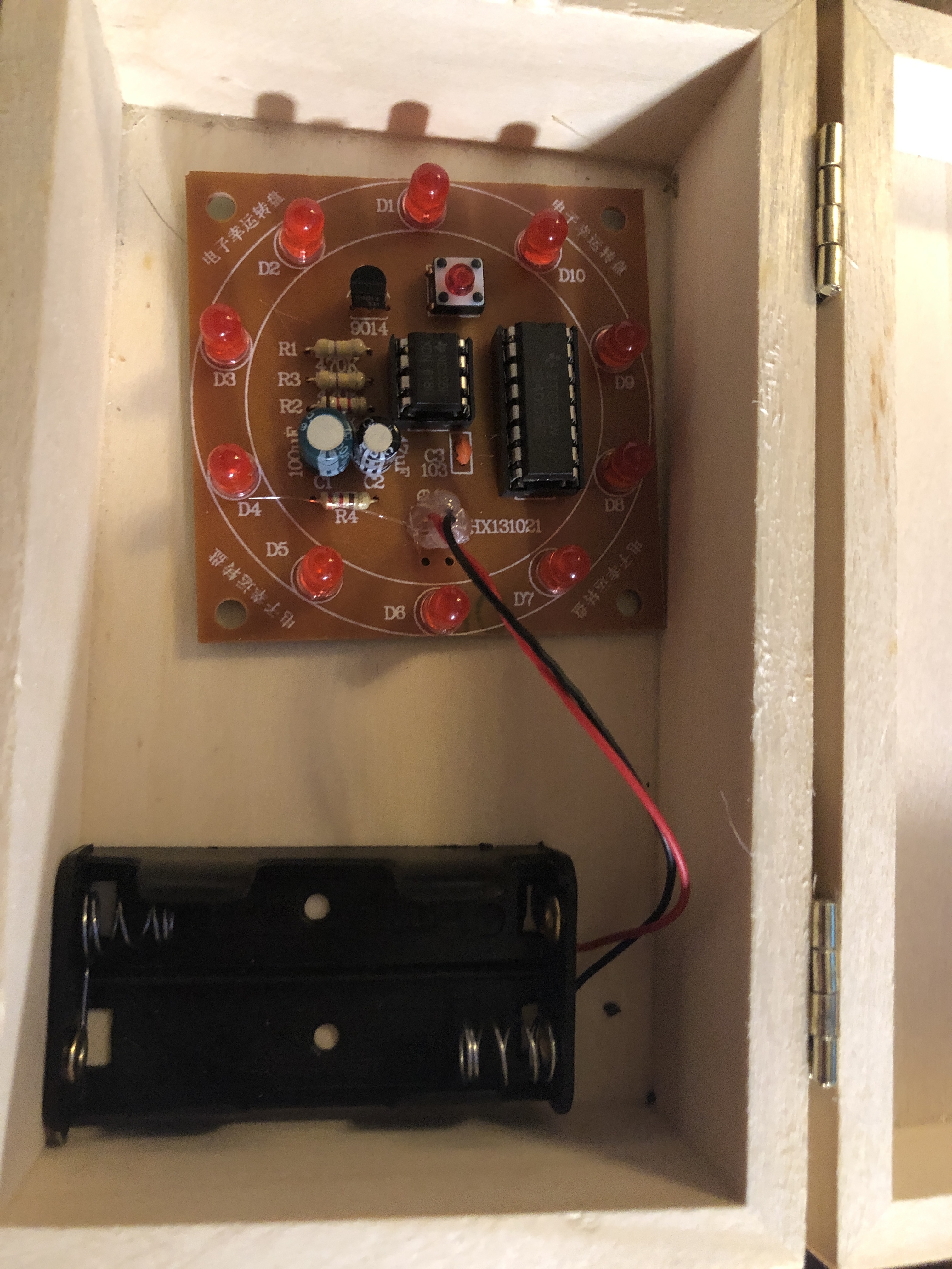
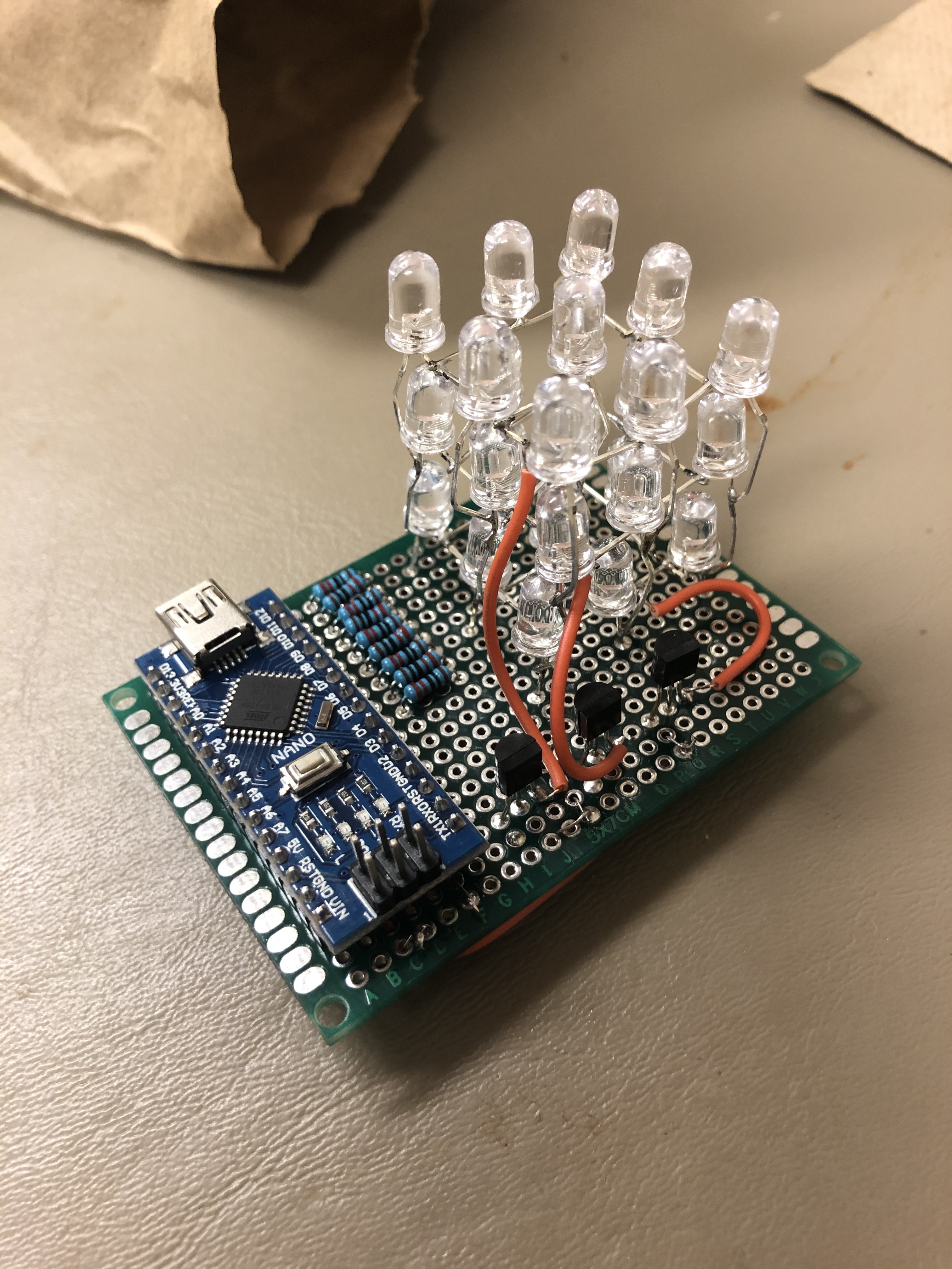
Made this from instructions online and parts I ordered.
No kit this time
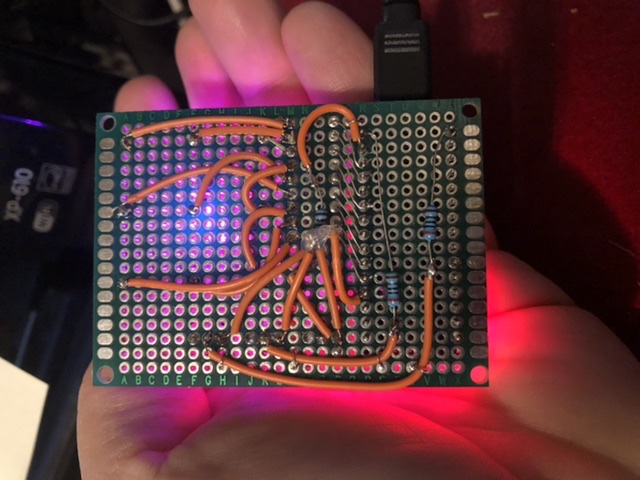
The pattern is screwy, the code I used (and yes have been looking at to figure out how it works) apparently thinks I made it z pattern but I made it q pattern
I do want to redo the orange earth wires they look out of place,
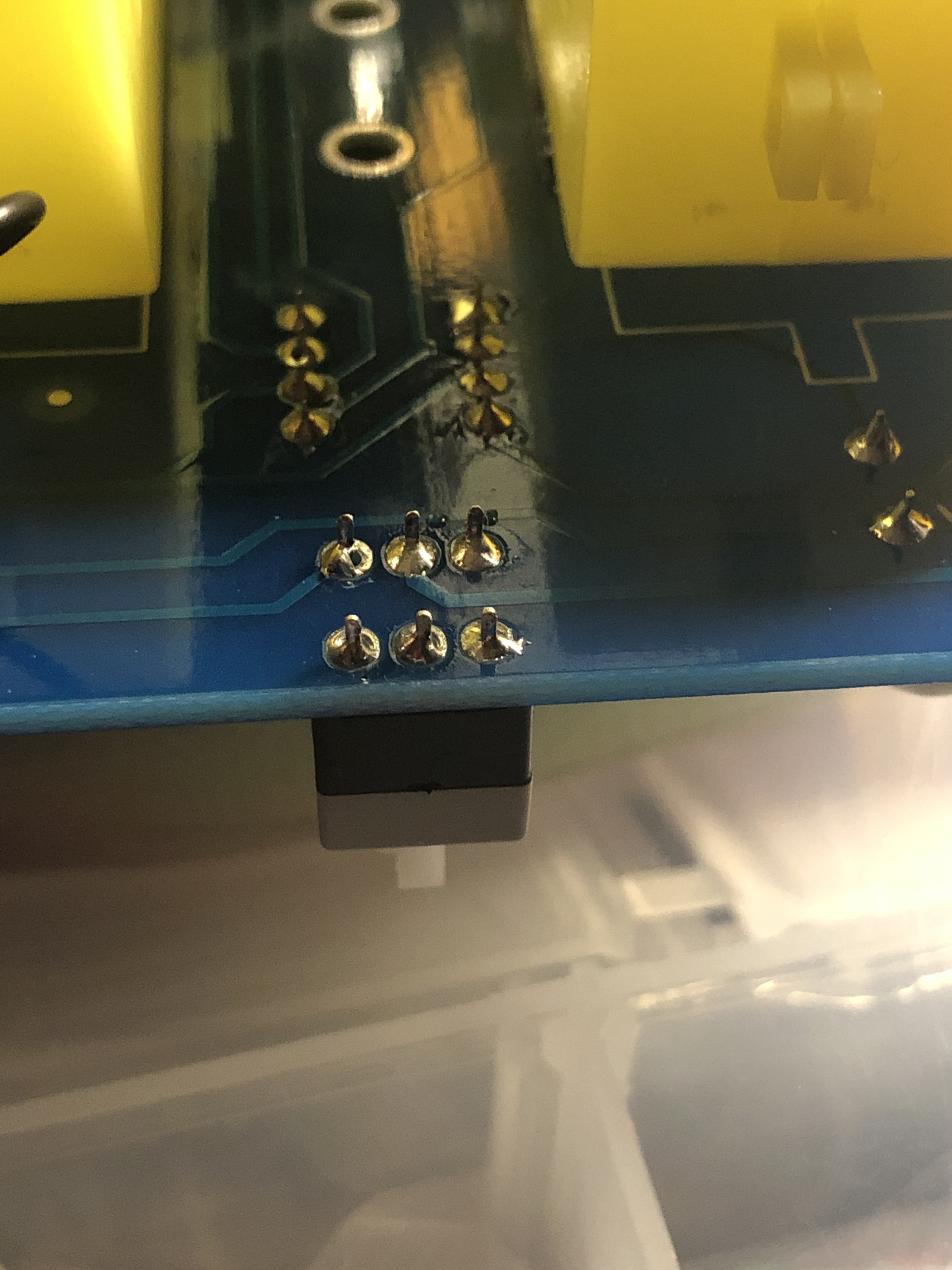
And the underside.
I didn’t have any heat shrink and I had to secure that one resistor and insulate those three wires from the transistors.
I only used a tiny bit honest.
I was gonna use a piece of resistor lead to tie the resistor down but where it is I couldn’t. I did tie down the wires though.
So I finally put my little metal detector kit together, it didn’t work, checked it tonight and two of the ceramic disc capacitors are apparently dead. Luckily I have more though I’ll test them first but need desoldering braid first.
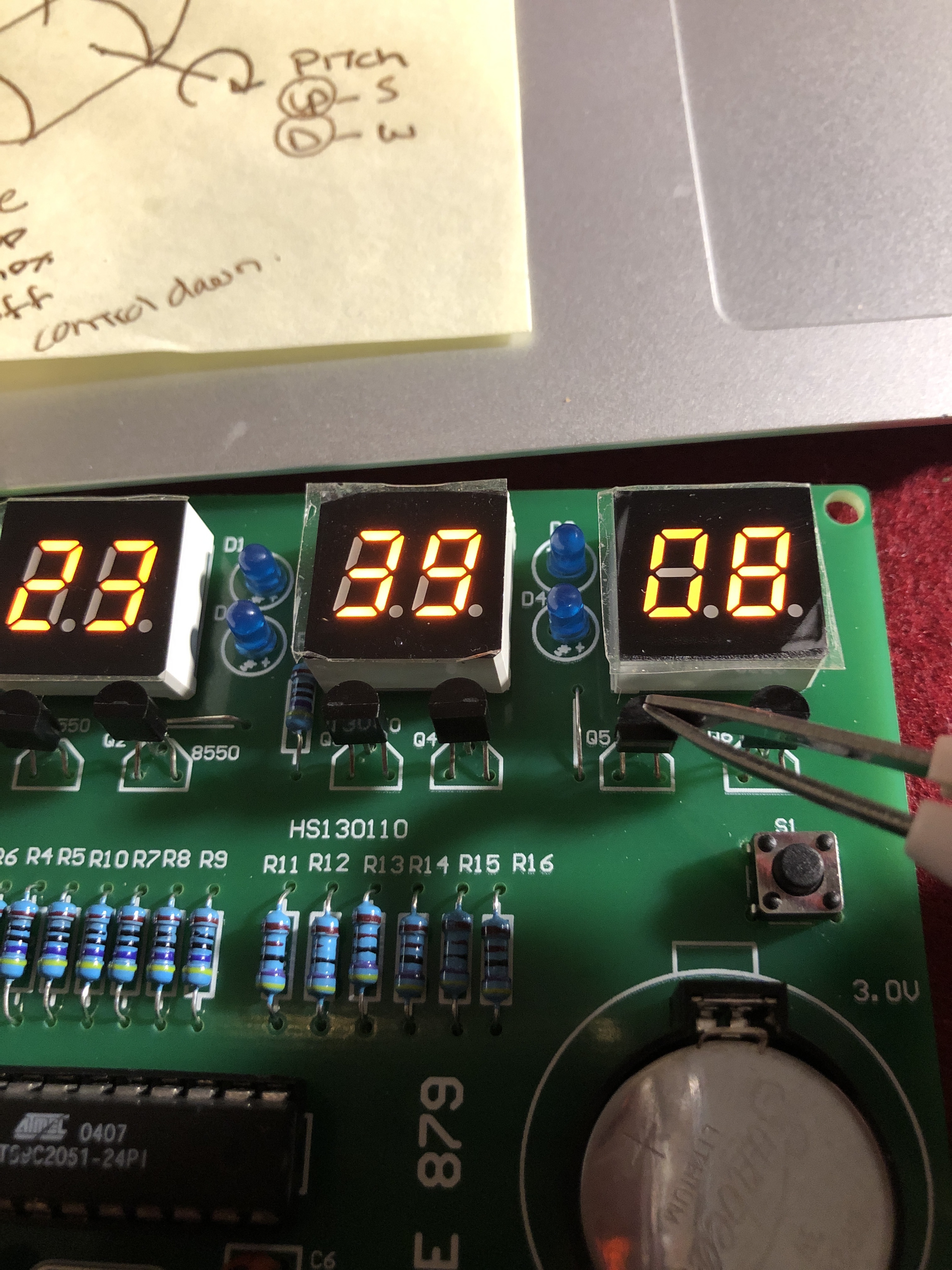
Everything works except the tens position in seconds, but when I short the base and collector of the transistor I’m touching with the tweezers it works, is that transistor bad?
Also for some reason the leds don’t light, I think it needs closer to the max voltage of 12 volts rather than the 5 I’m giving it atm.
A bit hard to say without knowing more about the circuit, but from the description alone it sounds like the transistor does what it is supposed to. Maybe the thing that is supposed to turn the transistor on (ie, signals the base) isn’t doing so? Maybe a bad solder joint between the two?
 and I had to secure that one resistor and insulate those three wires from the transistors.