Additionally, on 5V tolerance - from the datasheet: “5 V tolerant I/O pins; only valid when the VDD(IO) supply voltage is present” and “When configured as analog input, digital section of the pad is disabled and the pin is not 5 V tolerant”.
EDIT: Good news is that I2C as I suggested above should be fine, as those two pins are the exception to the rule: “Applies to all 5 V tolerant I/O pins except true open-drain I2C-bus pins PIO0__4 and PIO0__5, 5.5 V can be applied to these pins when VDD(IO) is powered down, compliant with the I2C-bus standard”.
BTW I have tried shorting the PEX pins into output pins, constant short, temporary. So far I have not been able to “kill” the device with its own voltage, no matter how I short them. Edit: I think one of you warned against shorting vdd to a low output pin. As far as I have tried, it has no effect.
Note that both SPI and I2C are really only meant for component to component, on the same board, or board to board over short distances. The same would be true for direct pin to pin UART connections.
If the goal is to connect over longer distances, you could consider using a pair of TTL to RS232 converter modules with the UARTs.
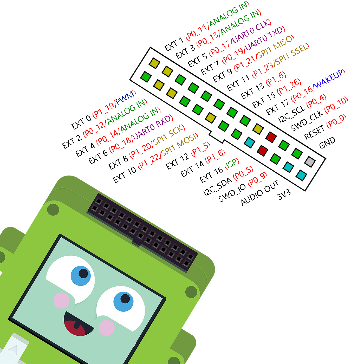
Yellow is 5V tolerant unless it’s being used as an analogue input.
Red is not 5V tolerant.
Grey is ‘not applicable’
GND should be fine with 5V right? The point of ground is to drain the power (or something like that)?
Cyan is “I don’t know, there was no P to match to the data sheet”
I suspect 3v3 should be grey since it’s an output
I’ll wait for someone else to double-check that before I go adding it to the PEX page.
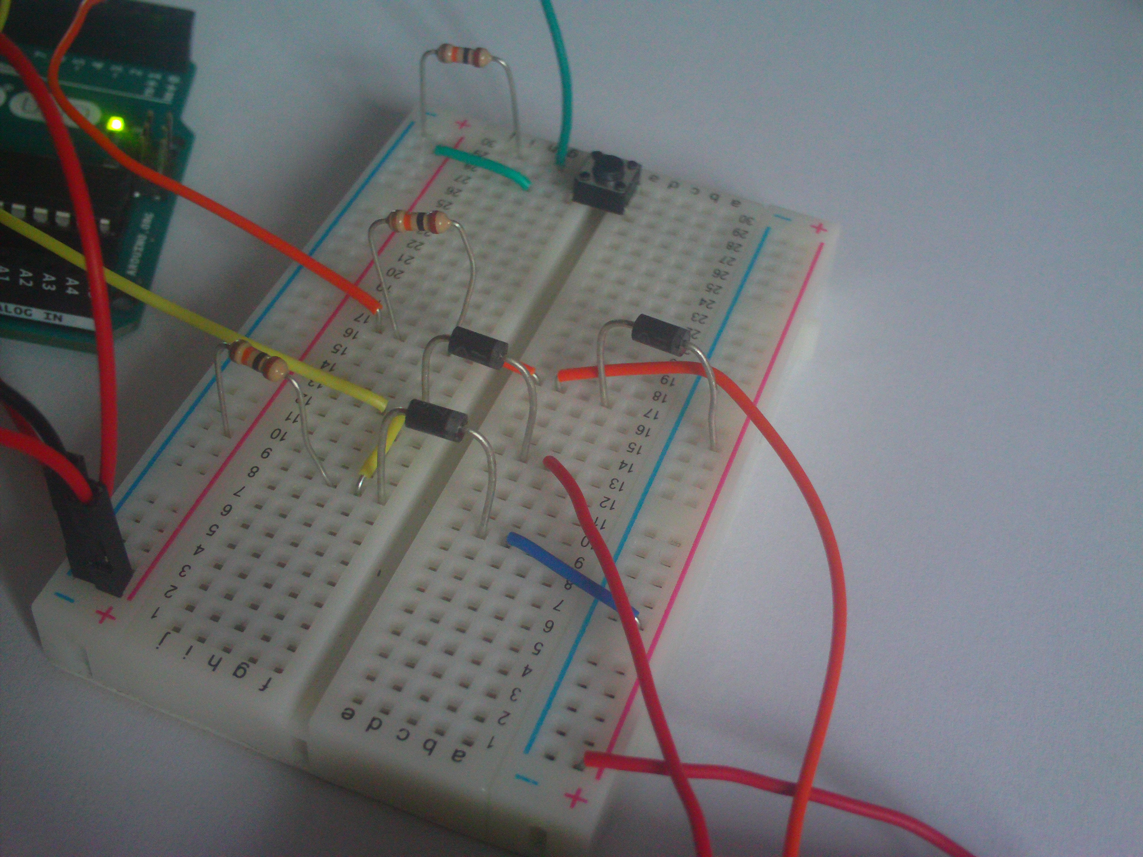
Anode (+) long, cathode (-) short.
I’m not sure if I’ve got a plain old signal diode in my box of tricks, I’ll have to check.
Those bullet points are very useful, thanks.
According to the data sheet, some aren’t when they’re cofigured as analogue inputs (category [3] and category [4]).
I won’t be doing that anyway, but it’s something to be wary of.
Do you mean remove the chip?
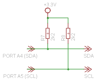
@uXe that sounds promising, but I think I’d understand it better with a diagram.
Or at least with an idea of which pull up resistors I’m configuring to what value.
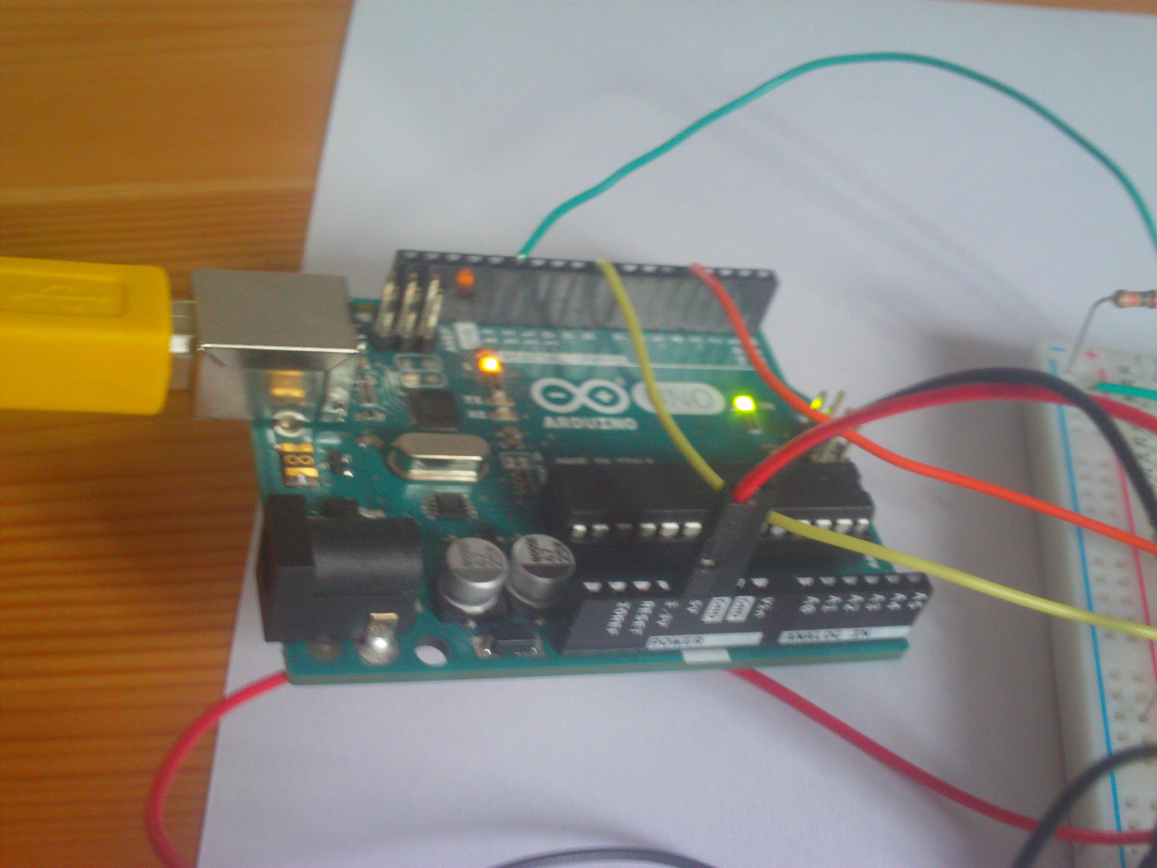
I can locate the Pokitto’s I2C ports and I’ll look the Uno’s up later, but I don’t know which resistors I’m hooking up to what.
I spotted that. The reason I took so long to start replying was because I was checking every pin and its caveats.
Whereabouts is that?
When I looked at the table both the I2C pins were marked as cat [7], which is:
I2C-bus pin compliant with the I2C-bus specification for I2C standard mode, I2C Fast-mode, and I2C Fast-mode Plus. The pin requires an external pull-up to provide output functionality. When power is switched off, this pin is floating and does not disturb the I2C lines.
Open-drain configuration applies to all functions on this pin.
Why do the grounds have to be linked?
Overall that does seem easiest. I’m not worried about speed yet.
This is one of my bigger concerns.
I’ve never attempted to hook a 3.3V board up to a 5V board and I don’t want to get it wrong in case I damage the Pokitto.
A good idea if I end up wanting to do this a lot.
For the time being I’d rather attempt to do it using parts I already have though.
Distance is not an issue and probably won’t be an issue.
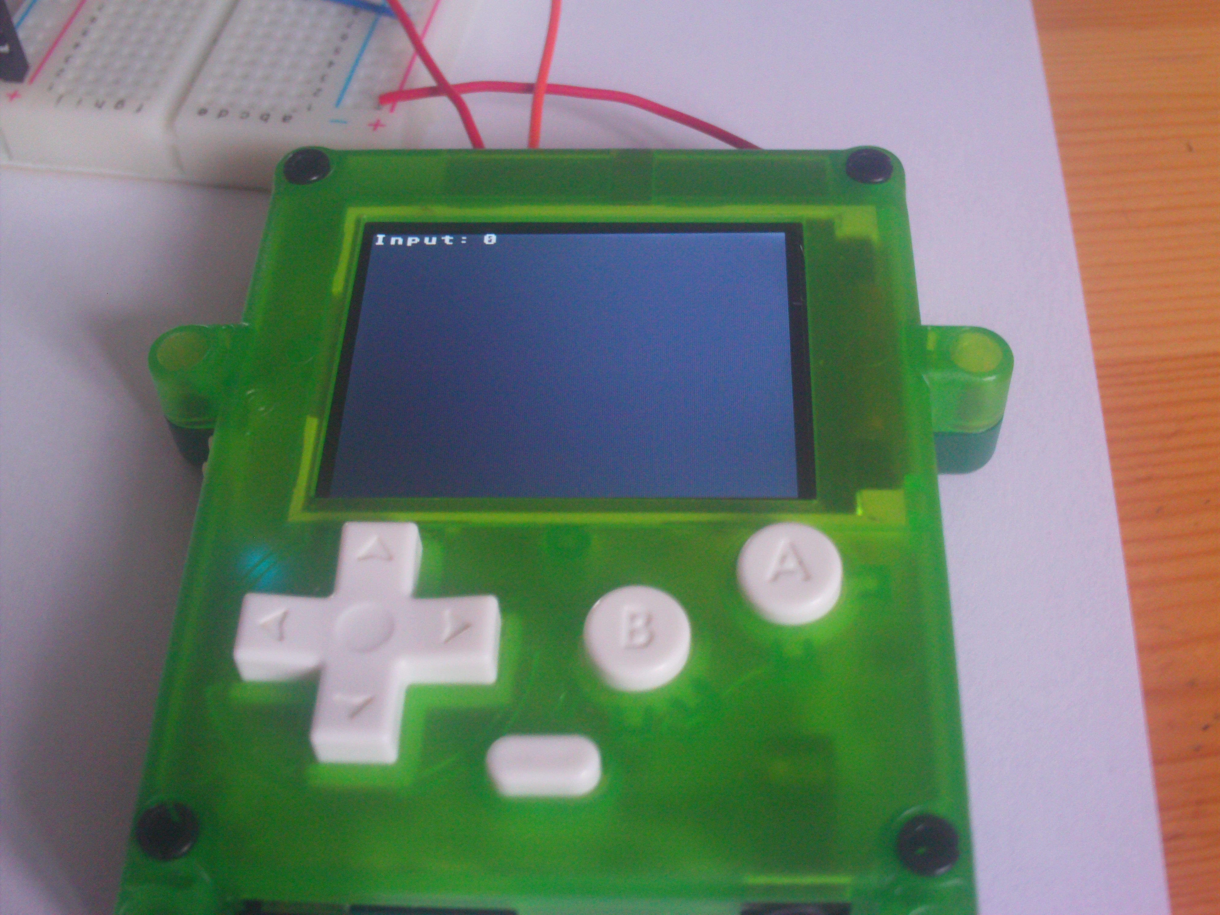
For the moment I’m just attempting a proof of concept experiment.
(The ground is often used as a reference of 0V. If you connect the local 5V to the local 0V, you’re essentially shortcutting the power source. When communicating with a system powered by another source, you need a reference voltage somewhere - usually GND is that reference voltage, but sometimes you get 5V or 3.3V voltage like I2C does)
No, the Uno uses those two pins for USB serial. It would be possible on a Leonardo for example though, because it uses a separate serial interface for USB, and the TX(1) amd RX(0) pins are referenced as Serial1 instead.
You could always use a ‘SoftwareSerial’ library though, and choose any two pins you like.
As @MLXXXp mentioned, if you go with I2C, connect the grounds of the Uno & Pokitto as well.
I’ve decided to attempt I2C next because that diagram looks easiest if it doesn’t have any 3.3V/5V issues.
I’ve just read into Ohms law, so I understand the equation, but I don’t know how to derive the values.
I’ve decided to dig around for some guides and diagrams and I’ve found an arduino one that looks quite promising.
Interestingly it notes:
There has been some confusion about the minimum voltage for a ‘high’ level. For the normal digital input pins of the ATmega328p this is 0.6 * Vcc. However, for the I2C pins it is 0.7 * Vcc
So actually that’s 3.5V, not 3V which possibly complicates matters.
I’ve seen the “Philips Applications Note AN97055” thrown around a lot.
If a BC547 is a sufficient replacement for the mosfets in the diagram then I could certainly attempt that set-up.
I may opt for that if I struggle with I2C.
I only have a vague idea of what I’m doing, like a BASIC programmer trying to write C code.
I’m not even sure where the crystal is located, but since I’d need the USB serial, that’s probably not the best option.
At the moment speed isn’t the issue, I just want a way to be able to transmit data of a reasonable size (e.g. 8 bits in one function call).
i think arduino wire is exactly 8 bits via spi, wire is also for i2c
i2c is probebly the easiest one to work with and also easyer to chain with mutliple devices if need be (arduino and esp32 and whatever else you want :P)
…or just pull-up to 5V instead if it has been established that the Pokitto’s I2C pins are fine with that? Could use one of your diodes for a small voltage drop, to have something-slightly-less-than-5V to pull-up to?
I only have two kinds of transistors and I’ve only got one of the other kind,
so at this rate, yeah, it’s looking like I probably am just best off ordering some new parts.
One idea I did have was to somehow abuse an optocoupler to isolate the two halves of the circuit, but I think I’d need more than one and frankly I don’t know if it’s a good idea or not anyway.
Hrm, I’ll mull it over a bit.
(Electronics is hard, I think I prefer template metaprogramming :P)

 …could try anyway and see how reliable or not it is?